
In Electronics Manufacturing, the bill of materials (BOM) serves as the foundational document that bridges design intent with manufacturing reality. This seemingly simple spreadsheet lists every component required to build a printed Circuit Board Assembly (PCBA)—from resistors and capacitors to ICs and connectors. Yet despite its humble appearance, BOM accuracy can make or break an entire production run.
Industry research consistently shows that over 60% of production line abnormalities in Smt Assembly trace back to BOM-related errors. These errors cascade through the manufacturing process, causing delays, driving up costs, and frustrating both manufacturers and their customers. Understanding why BOM accuracy matters—and how to achieve it—represents a critical competency for any organization involved in electronics production.

A bill of materials for Pcb Assembly goes far beyond a simple shopping list. It serves as the master reference document that guides every aspect of the production process:
When the BOM contains errors, every downstream process suffers. A single incorrect component designation can halt an entire production line, trigger expensive rework, or—worst case—result in field failures that damage customer relationships and brand reputation.
One of the most frequent BOM errors involves part numbers that don't match actual components. This can occur when engineers use internal part numbers that differ from manufacturer part numbers, or when they specify an obsolete component without noting the replacement. The result: procurement orders the wrong parts, which either fail to match PCB footprints or arrive too late for production schedules.
Incomplete part numbers present another variant of this problem. Specifying only "10μF capacitor" without voltage rating, dielectric type, or case size leaves too much room for interpretation. A 10μF ceramic capacitor and a 10μF electrolytic capacitor may share the same capacitance value but have vastly different electrical characteristics, temperature coefficients, and physical footprints.
Component designators (R1, C5, U12) must match exactly between the BOM, PCB Silkscreen, and schematic symbols. When these designators don't align, assembly teams face impossible decisions: follow the BOM or follow the board markings?
Missing components represent an especially costly error type. A BOM that omits even a single passive component forces production to stop while engineering determines what belongs in the empty slot. For high-mix production environments running multiple board variants, such discoveries can cascade across multiple SKUs.
BOMs sometimes list incorrect quantities for components. This might seem like an obvious error that would be caught in review, but in practice, quantity errors slip through surprisingly often. Engineers might specify the quantity of a resistor used in a single circuit when the board actually contains four parallel instances. Or they might miss a component that appears twice on the schematic but only once on the BOM.
The consequences of quantity errors range from component shortages (stopping production) to component surpluses (wasted inventory and financing costs).
Specifying a component with the correct electrical parameters but the wrong package type creates a critical assembly problem. The component simply won't fit the PCB pads designed for it. For example, specifying an 0402 resistor when the PCB uses 0603 pads means that part cannot be placed—no amount of rework can solve this mismatch.
Package mismatches often arise when engineers specify "preferred" or "equivalent" components without confirming package compatibility. Substitute parts may have identical electrical specifications but different physical dimensions.
Outdated BOM versions represent an organizational failure that can waste entire production runs. An engineer updates the PCB to Rev 2.0 but manufacturing still operates from the Rev 1.0 BOM. The resulting mismatch between physical board and component list causes assembly failures, inspection rejections, and finger-pointing between departments.
Version control issues become especially problematic in organizations with multiple design teams, distributed manufacturing, or long production cycles where design iterations occur during active builds.
BOM errors generate immediate direct costs that are easy to quantify:
Industry benchmarks suggest that BOM-related errors typically add 5% to 15% to production costs for affected boards. For expensive multilayer PCBs with high-value components, absolute dollar losses can reach tens of thousands per incident.
Beyond direct costs, BOM errors generate hidden expenses that often exceed the visible impact:
Some organizations estimate that hidden BOM error costs run 4 to 5 times higher than direct measurable losses. The customer who leaves because of consistent quality issues represents losses that never appear in any cost accounting.
Establish mandatory fields for every BOM entry. A complete BOM should include:
Standardized formats reduce interpretation errors and enable automated validation tools to check for completeness.
Never release a BOM to production based on a single engineer's review. Effective BOM validation involves:
Each review layer catches different error types, and the multiplicative effect dramatically reduces total error rates.
Manual BOM review cannot catch every error. Automated tools provide essential verification capabilities:
Modern EDA tools increasingly incorporate BOM validation features, and specialized Bom Management software offers even more sophisticated checking capabilities.
Implement formal version control procedures for all BOMs:
Some organizations implement BOM locks that prevent production releases until all validation checks pass, ensuring that only reviewed, approved BOMs reach manufacturing.
Component substitutions are sometimes necessary due to availability or cost considerations. Without clear policies, substitution decisions can introduce BOM errors:
Design For Manufacturability (Dfm) review provides an opportunity to catch BOM issues before they reach production. During Dfm, engineering teams examine the interaction between component selections, PCB layout, and assembly processes.
Effective DFM reviews validate:
Organizations that integrate Dfm Review into their development process consistently report lower BOM-related production errors and faster time-to-market.
BOM accuracy represents a foundational requirement for successful Pcb Assembly. What begins as a simple spreadsheet error cascades through procurement, warehouse, and production operations, generating costs that multiply far beyond the initial mistake. The financial impact—measured in line stoppages, rework, scrap, and customer dissatisfaction—can threaten project viability and long-term business relationships.
Achieving BOM accuracy requires systematic approaches: standardized formats, multi-level reviews, automated validation, strict version control, and clear substitution policies. Organizations that invest in BOM quality processes consistently outperform competitors who treat BOM creation as a clerical task rather than an engineering discipline.
In Electronics Manufacturing, the BOM is not merely a list of parts—it's the document that determines whether design vision becomes working hardware. Treat it accordingly.
A production-ready BOM should include: component designators, complete manufacturer part numbers, quantities, package types, and any approved substitutes. Without these elements, assembly teams lack the information needed to source correct parts and verify placement accuracy.
Best practices include cross-referencing against PCB layout files, validating part numbers against manufacturer databases, having multiple engineers review the document, and running automated validation tools. Some organizations also request a manufacturing Dfm Review before final release.
Contact engineering immediately for an approved substitute. Verify that the substitute matches footprint, electrical specifications, and thermal characteristics. Update the BOM with the substitution information and communicate the change to all stakeholders before continuing production.
BOMs should be updated whenever design changes occur, component substitutions are approved, or version-controlled documents require revision. At minimum, review BOMs against current inventory and production status before each production release.
BOM errors directly impact first-pass yield by causing incorrect component placement, assembly failures, and downstream quality problems. Industry data suggests that BOM-related errors can reduce yield by 5% to 15% on affected boards. Improving BOM accuracy is one of the most cost-effective ways to improve overall production efficiency.

Common Defects in PCB Assembly and How Manufacturers Prevent ThemSeptember/18/2026

Challenges in Manufacturing High Aspect Ratio Multilayer BoardsSeptember/07/2026
Handling Mixed Technology: Integrating SMT, THT, and Odd-form ComponentsAugust/12/2026
SMT vs THT PCB Assembly in China: Which Technology is Right for Your Project?June/10/2026
Inspection Standards: IPC-A-610 and What it Means for Your Assembled BoardsAugust/03/2026
The Benefits of Combining PCB Fabrication and AssemblyMay/22/2026
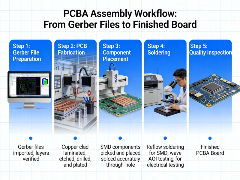
Understanding the PCBA Workflow: From Gerber Files to Finished BoardJune/16/2026

Prototyping vs. Production Assembly: Different Approaches for Different StagesSeptember/08/2026