Open Nav
In the complex world of Electronics Manufacturing, the bridge between design and production is built on precision, expertise, and meticulous attention to detail. Computer-Aided Manufacturing (CAM) engineering serves as this critical bridge, transforming design concepts into manufacturable realities while preventing costly errors that can derail production timelines and compromise product quality. The role of CAM engineering in preventing manufacturing errors extends far beyond simple file conversion—it encompasses comprehensive design analysis, process optimization, and quality assurance that safeguards the entire manufacturing workflow.
CAM engineering represents the intersection of design technology and manufacturing processes, where sophisticated software tools and human expertise combine to ensure successful production outcomes. At its core, CAM engineering involves the processing and optimization of design files—typically in formats like Gerber, ODB++, or DXF—into the precise instructions and data sets required by manufacturing equipment. This transformation is far from straightforward, as it requires deep understanding of both design intent and Manufacturing Capabilities, material properties, and process limitations.
Modern CAM systems, such as CAM350, Genesis, or specialized manufacturer-developed platforms, provide automated analysis capabilities that can detect thousands of potential issues before production begins. However, the true value of CAM engineering emerges when automated tools are guided by experienced engineers who understand the nuanced interplay between design choices and manufacturing outcomes. Research indicates that 70% of PCBA quality problems originate from design-stage oversights, making CAM engineering's preventive role particularly crucial in the overall quality management framework.
Design For Manufacturability (Dfm) checks constitute the first and perhaps most important line of defense against manufacturing errors. CAM engineers perform comprehensive Dfm analysis that validates every aspect of a design against Manufacturing Capabilities and quality standards. This process involves systematic examination of layer structures, trace widths and spacing, pad sizes and shapes, hole specifications, solder mask requirements, and countless other design elements that directly impact manufacturability.
Advanced DFM tools automatically identify violations such as insufficient clearance between conductors, inadequate annular rings on plated through-holes, non-standard hole sizes that may require special tooling, and trace widths below minimum fabrication capabilities. For instance, if Gerber Files specify line widths/spacings smaller than a factory's minimum capability (such as 4/4mil), CAM engineers must either automatically adjust these values through CAM software or flag the issue for design modification. This proactive approach prevents manufacturing failures that could otherwise cost thousands of dollars in scrap and rework.
Sophisticated DFM software can perform thousands of checks in seconds, comparing design parameters against manufacturing rules and standards. These automated systems check for netlist errors, copper pour spacing violations, insufficient copper ring widths, incorrect layer stacking, missing apertures, and numerous other potential issues. The power of automated DFM lies in its consistency and comprehensiveness—unlike human inspectors, software never gets tired, never overlooks standard violations, and maintains the same rigorous standards across every design review.
While automated DFM tools provide invaluable assistance, experienced CAM engineers bring critical judgment that software cannot replicate. They understand the manufacturing context behind every design rule, can identify potential issues that fall outside standard parameters, and make nuanced decisions about when to modify designs versus when to recommend alternative manufacturing approaches. This human expertise is particularly valuable for complex designs involving mixed technologies, specialized materials, or novel applications that may not fit standard DFM rules.
CAM normalization represents the systematic process of converting diverse customer design files into standardized, manufacturing-ready formats. This crucial step ensures consistency across different designers, software tools, and file formats while aligning with specific manufacturing equipment capabilities. During normalization, CAM engineers address file format inconsistencies, standardize layer naming conventions, ensure proper coordinate systems, and create the precise data structures needed for production equipment.
The normalization process also includes creating comprehensive Manufacturing Instructions (MI) that communicate critical processing requirements to production personnel. These instructions specify layer sequencing, copper weights, solder mask requirements, surface finish specifications, special processing needs, and quality control requirements. Without proper CAM normalization, manufacturers risk CAM holds—production stoppages caused by inconsistent or incomplete design data that prevents manufacturing from proceeding.
CAM holds occur when customer Pcb Design files contain inconsistencies that prevent manufacturers from proceeding with production. These holds can result from discrepancies between Gerber file specifications and order requirements, missing essential files such as aperture lists or drill files, netlist comparison errors revealing insufficient copper rings or trace width violations, or incompatibility between design specifications and manufacturing capabilities. Effective CAM normalization prevents these costly delays by identifying and resolving issues before they reach the production floor.
Industry studies suggest that proper CAM normalization can reduce manufacturing delays by up to 40% and significantly improve first-pass yields. By standardizing data formats, verifying completeness, and ensuring alignment with manufacturing capabilities, CAM engineers create smooth transitions from design to production that avoid common pitfalls that plague inexperienced or inconsistent CAM practices.
CAM engineering serves as a critical quality control function that extends well beyond simple file preparation. Through comprehensive analysis and verification, CAM engineers identify quality risks that could manifest during manufacturing or product operation. This preventive approach to quality control is far more effective than post-production inspection, as it addresses problems at their source rather than detecting failures after they've occurred.
Comprehensive design verification ensures that all aspects of the design meet both functional requirements and manufacturing standards. CAM engineers verify netlist integrity, check for unintended connections (shorts) or missing connections (opens), validate pad-to-hole relationships, and ensure proper power distribution network design. This verification process catches electrical design errors that could cause functional failures, as well as manufacturing issues that could compromise reliability or yield.
Every manufacturing facility has specific capabilities and limitations that must be considered during CAM engineering. Process capability alignment involves matching design requirements with manufacturing capabilities through intelligent trade-offs and optimizations. When design requirements exceed standard manufacturing capabilities, CAM engineers may recommend process modifications, design adjustments, or alternative approaches that achieve the required results while maintaining manufacturability and cost-effectiveness.
Modern CAM engineering employs sophisticated error detection techniques that go beyond basic DFM checks. These advanced capabilities include acid residue detection, isolation verification, Signal Integrity analysis, and thermal performance evaluation. By leveraging these advanced analysis tools, CAM engineers can identify subtle issues that might escape standard inspection but could cause field failures or reliability problems.
Acid etching defects, such as acid residue or isolated copper islands, represent serious manufacturing concerns that can cause short circuits or reliability issues. CAM engineering tools can automatically detect potential acid etching problems by analyzing copper distribution, identifying isolated copper features that may not be properly removed during etching, and flagging areas where etching process parameters may need adjustment. For example, CAM350 analysis can identify copper traces located more than 0.5mm from the main copper pattern that may represent acid residue risks.
Netlist comparison provides powerful verification of electrical connectivity by comparing the designed circuit topology with the actual layout implementation. This automated analysis can detect missing connections, unintended shorts, and other electrical errors that could cause functional failures. Sophisticated CAM tools perform netlist comparison across multiple design representations—schematic netlists, Pcb Layout data, and extracted netlists from Gerber Files—to ensure complete consistency and accuracy.
Beyond error prevention, CAM engineering drives continuous process improvement through optimization of tooling, processing parameters, and production workflows. Experienced CAM engineers identify opportunities to reduce manufacturing time, improve yield, lower costs, and enhance quality through intelligent process design and optimization.
CAM engineers optimize tooling selection and usage patterns to improve manufacturing efficiency and quality. This includes selecting optimal drill bit sizes and types, planning efficient drilling paths that minimize tool changes and travel time, optimizing routing paths for CNC milling equipment, and selecting appropriate processing sequences that minimize thermal stress and warpage. Tooling optimization can reduce processing time by 20-30% while improving quality consistency.
Effective CAM engineering considers the complete manufacturing process from materials selection through final inspection. Engineers optimize material stack-ups for manufacturability, specify appropriate processing parameters for specific material combinations, and design process flows that minimize defects and maximize yield. This holistic approach ensures that design decisions align with material properties and process capabilities throughout the manufacturing chain.
CAM engineering delivers significant cost benefits through error prevention, process optimization, and waste reduction. By catching design issues before production begins, CAM engineers avoid the substantial costs associated with scrap, rework, and production delays. Process optimization reduces manufacturing time and resource consumption, while quality improvements reduce inspection and warranty costs.
Industry data suggests that comprehensive CAM engineering can reduce overall manufacturing costs by 15-25% through these combined effects. The cost of performing thorough CAM analysis represents a small fraction of the savings achieved through prevented errors and optimized processes. This makes CAM engineering one of the highest-return investments in Electronics Manufacturing.
The field of CAM engineering continues to evolve with advancing technology and increasing manufacturing complexity. Artificial intelligence and machine learning are beginning to enhance CAM capabilities, enabling more sophisticated analysis and prediction of manufacturing outcomes. Cloud-based CAM systems are improving collaboration between designers and manufacturers, while advanced simulation tools enable virtual prototyping and process verification before physical production begins.
Despite technological advances, the human element remains essential to CAM engineering success. Experienced engineers bring contextual understanding, judgment, and creativity that software cannot replicate. The most effective CAM strategies combine automated tool capabilities with human expertise to create comprehensive error prevention and process optimization programs.
CAM engineering serves as the critical foundation for successful electronics manufacturing, preventing errors that could otherwise derail production, compromise quality, and increase costs. Through comprehensive DFM analysis, meticulous normalization, advanced error detection, and continuous process optimization, CAM engineers ensure that designs transition smoothly from concept to manufactured reality.
The investment in robust CAM engineering processes delivers substantial returns through improved yield, reduced rework, faster time-to-market, and enhanced product reliability. As electronic designs become increasingly complex and manufacturing requirements continue to tighten, the role of CAM engineering in preventing manufacturing errors will only grow in importance. Organizations that recognize and invest in this critical function will maintain competitive advantages in quality, cost, and delivery performance.
Success in modern electronics manufacturing requires acknowledging that manufacturing excellence begins with design—specifically, with the CAM engineering processes that transform design data into manufacturable information. By making CAM engineering an integral part of the design-to-manufacturing workflow rather than an afterthought, manufacturers can prevent errors before they occur, optimize processes for maximum efficiency, and achieve consistently high quality across all production runs.
The primary role of CAM engineering is to bridge the gap between electronic design and physical manufacturing by processing design files into production-ready formats while preventing errors through comprehensive DFM analysis, quality checks, and process optimization. CAM engineers transform design concepts into manufacturable realities while ensuring compatibility with manufacturing capabilities and quality standards.
DFM analysis prevents manufacturing errors by systematically validating every design element against manufacturing capabilities and quality standards before production begins. This process identifies issues such as insufficient trace spacing, inadequate pad sizes, non-standard features, and manufacturing rule violations that could cause production failures, allowing for corrections before expensive manufacturing processes begin.
CAM normalization is the process of converting diverse customer design files into standardized, manufacturing-ready formats that align with specific manufacturing equipment capabilities. This process ensures consistency, prevents CAM holds (production delays caused by data inconsistencies), and creates smooth transitions from design to production by addressing file format issues, standardizing conventions, and verifying completeness.
CAM engineering reduces manufacturing costs by preventing errors that would cause scrap and rework, optimizing tooling and processes to improve efficiency, reducing production delays through proper data preparation, and improving yields through quality-focused design analysis. Industry data suggests comprehensive CAM engineering can reduce overall manufacturing costs by 15-25%.
CAM engineers use specialized software tools such as CAM350, Genesis, ODB++ viewers, and manufacturer-developed platforms that provide automated DFM analysis, netlist comparison, design verification, and process optimization capabilities. These tools perform thousands of checks to detect potential issues while enabling experienced engineers to apply judgment and expertise to address complex challenges.
How to Find the Right PCB Fabrication Partner in ChinaJune/02/2026
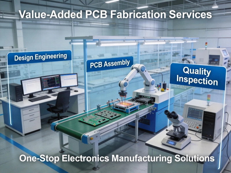
Value-Added PCB Fabrication Services: Beyond Just Making the BoardJune/12/2026

Engineering Support: How Good Service Providers Help Optimize Your DesignJuly/02/2026
The Advantages of HDI PCB Fabrication for Compact ElectronicsMay/22/2026
How Chinese Manufacturers Ensure Precision in the SMT PCB Assembly ProcessJune/03/2026
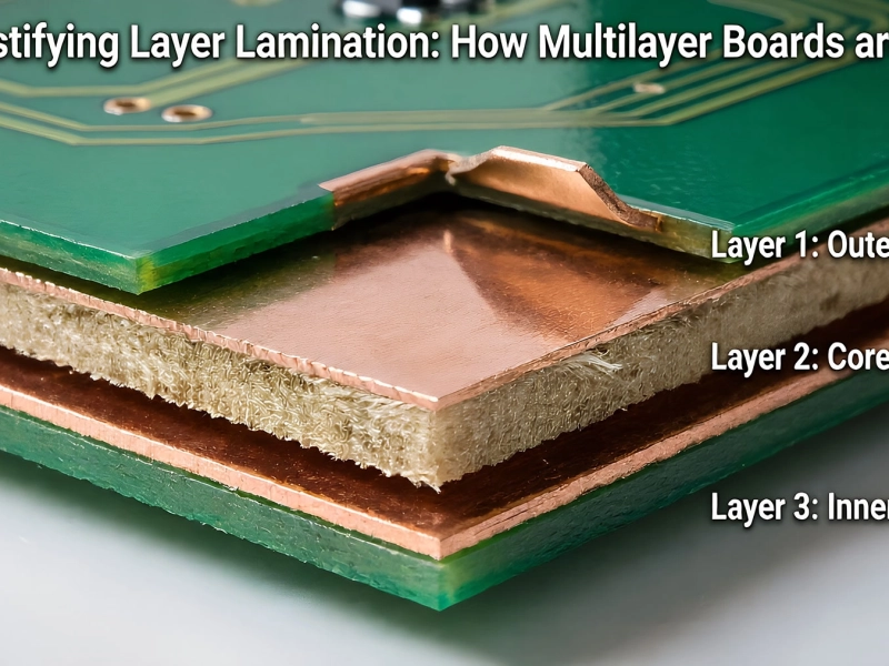
Demystifying Layer Lamination: How Multilayer Boards are BuiltJune/05/2026
Top Trends Shaping the Chinese PCB Manufacturing Industry in 2026May/21/2026

How AI-Driven Scheduling is Making Rapid PCB Prototyping More ReliableJune/18/2026