
The electronics industry has spent decades miniaturizing products while expanding functionality. But here's a challenge that conventional rigid circuit boards can't always solve: how do you connect electronics in devices that bend, fold, or take irregular shapes? The answer lies in flexible and rigid-flex printed circuit boards — technologies that have quietly revolutionized everything from smartphones to medical implants.
If you're still designing around flat, rigid boards only, you're limiting your product's potential. Flexible PCBs open up entirely new design paradigms: wearables that conform to the body, foldable phones with hinges that fold thousands of times, automotive dashboards with curved surfaces, and medical devices small enough to fit inside blood vessels. This guide walks you through everything you need to know about incorporating flexible and rigid-flex designs into your next product.

A flexible printed circuit consists of a thin, bendable dielectric substrate with copper circuits laminated to it. Unlike rigid FR4 boards, flexible circuits can fold, bend, and twist to fit the mechanical envelope of your product rather than forcing the product to accommodate the board's shape.
The base material for flexible circuits is typically Polyimide (PI) or polyester (PET). Polyimide dominates for demanding applications because it handles higher temperatures, resists chemicals, and maintains mechanical properties across wide temperature ranges. PET works for cost-sensitive applications with less stringent thermal requirements but can't withstand Reflow Soldering temperatures without special handling.
Copper in flexible circuits is almost always rolled-annealed (RA) rather than electrodeposited (ED). RA copper has superior flexibility because its grain structure aligns with the bend direction, allowing it to withstand repeated flexing without developing cracks. ED copper's columnar grain structure makes it prone to fatigue failure at bends — a critical difference for dynamic flex applications.
Not all flexible circuits are created equal. Different constructions serve different purposes, and understanding these options helps you specify the right design for your application.
The simplest flexible construction has copper traces on one side of the dielectric substrate with a coverlay protecting the circuits. These work well for simple interconnects, cable replacements, and applications where the board bends in a single plane with minimal dynamic movement. Cost-wise, single-sided flexible circuits offer the most accessible entry point into flexible PCB technology.
Adding copper and circuitry to both sides of the substrate enables more complex routing and allows cross-overs without additional layers. Through-hole plating connects the two sides, and the circuits can route around obstacles in ways impossible with single-sided designs. Double-sided flexible circuits support higher circuit density and more sophisticated applications while remaining relatively straightforward to manufacture.
For complex applications requiring many signals, multilayer flexible circuits stack multiple copper layers with insulating layers between them. This construction enables intricate routing but requires careful attention to layer counts and materials to maintain flexibility. Multilayer flex typically uses adhesive-less constructions to handle the thermal demands of multiple laminations without compromising flexibility.
The real magic happens when you combine rigid and flexible sections in a single board. Rigid-flex PCBs have rigid sections where components mount and dense routing lives, connected by flexible sections that bend to create hinges, fold lines, or 3D packaging. This combination captures the best of both worlds: component mounting density where you need it and mechanical flexibility where space is constrained.
The benefits of flexible circuit technology extend beyond just fitting into unusual shapes. Understanding these advantages helps you recognize when flexible designs belong in your product roadmap.
Flexible circuits eliminate the need for connectors, cables, and wire harnesses that rigid boards require to interface with other parts of a product. A flexible circuit can fold directly onto itself, routing signals between rigid sections without connectors that consume space and add cost. This integration typically reduces weight by 60-75% compared to equivalent rigid board plus wiring assemblies.
The thickness savings compound over the product lifecycle. Replacing a wiring harness with a flexible circuit in an automotive application might save 5-10mm in packaging thickness. That might not sound like much, but in a packed instrument cluster or center console, it can enable features that wouldn't fit otherwise.
A properly designed flexible circuit with good strain relief actually outperforms wire harnesses in high-vibration environments. Wires fatigue at their termination points where flexing concentrates stress. Flexible circuits distribute strain more evenly across the bend radius, and the integral connection between traces and pads eliminates the solder joints that fail in wire harnesses.
The number of connection points drops dramatically with flexible circuits. Every connector in a wiring harness represents a potential failure point. Replacing multiple connectors and wire segments with a single continuous flexible circuit reduces failure modes and simplifies failure analysis when problems do occur.
Flexible circuits with Controlled Impedance are easier to manufacture consistently than cables with Controlled Impedance. The dihedral connections between trace and pad create impedance discontinuities in cable assemblies, but a flexible circuit maintains consistent geometry from end to end. This matters for high-speed signals like USB, HDMI, or MIPI interfaces that run through 90-degree or complex routing paths.
Flexible circuits also reduce EMI because the controlled geometry creates consistent return paths. Twisted wire pairs and loose cable routing create unpredictable radiated emissions, while flexible circuits with proper ground plane construction behave predictably.
This is where rigid-flex truly shines. By designing the board's shape to match your product's mechanical envelope, you eliminate the space reserved for cables, connectors, and wire routing. The flexible sections become structural elements of the product rather than afterthoughts that must be accommodated.
Fold a flexible circuit to create a hinge in a foldable device. Curve it around a housing wall. Stack rigid sections to create dense computing modules connected by flexible bridges. These configurations are simply impossible with conventional rigid boards and significantly expand what's achievable in product design.
Designing flexible circuits requires a different mindset than rigid board design. The same principles apply, but with important mechanical overlays that rigid designers rarely consider.
The most fundamental flex design rule is minimum bend radius. Bending a flexible circuit sharper than its minimum radius causes copper cracks, delamination, and premature failure. General guidelines suggest minimum bend radius of 6-12 times the circuit thickness for static bends and 12-24 times for dynamic flexing applications.
A 0.2mm thick flexible circuit should bend no sharper than 1.2mm radius for static applications and 2.4mm for dynamic flexing. These aren't arbitrary numbers — they're based on the strain that copper can withstand without fatigue. Exceed the recommended radius, and you're trading immediate failure for premature field failure after a few thousand flex cycles.
Every termination point on a flexible circuit is a stress concentration. Where the flexible circuit meets a rigid component pad, a connector, or even a stiffener, you need strain relief to prevent the copper traces from cracking at the interface. This typically means gradually transitioning from the flexible section to support structures, with no sharp transitions where flex begins.
Stiffeners mounted behind component termination points distribute stress away from the solder joints. These are usually FR4 or polyimide sheets bonded to the back of the flexible circuit in areas that shouldn't bend. They're essential at connector termination points, under heavy components, and anywhere mechanical forces might load the circuit.
Traces on flexible circuits should run perpendicular to bend lines whenever possible. Running traces parallel to a bend axis concentrates all the strain on the trace width, while routing perpendicular distributes strain along the trace length. This orientation difference can mean the difference between a circuit that survives 100,000 flex cycles and one that fails at 1,000.
Avoid routing traces across the center of bend zones — that region experiences the highest strain during bending. If you need signals in the middle of a flex region, route them on inner layers where strain is lower, or widen traces to provide more copper cross-section to handle the additional stress.
Coverlay protects exposed traces in flexible circuits, analogous to soldermask on rigid boards but with the additional requirement of maintaining flexibility. Window openings expose component pads, and these openings need appropriate size for the component and assembly process. Too small and you can't solder reliably; too large and you leave excessive copper exposed.
For component pads, consider using border pads or castellated edges for better solder joint reliability. These designs provide additional copper around the pad for better mechanical anchoring, which matters significantly in flex applications where thermal cycling and mechanical stress constantly challenge solder joints.
Flexible circuits have different manufacturing processes than rigid boards, and understanding these differences helps you design for producibility and avoid unnecessary cost premiums.
Flexible circuits require special handling throughout manufacturing because they're more susceptible to damage than rigid boards. They must be supported during depanelization, cleaned carefully to avoid kinking, and stored flat or on rolls depending on the construction. These handling requirements add cost, but experienced manufacturers have developed processes that handle flex reliably.
Panelization for flexible circuits typically uses different methods than rigid boards. Window panes with routed relief, tab-routing with snap ties, or laser cutting all see use depending on the design. Your manufacturer should specify the panelization method that's compatible with your design's flex zones and assembly requirements.
Polyimide offers superior performance but costs more than polyester. Adhesive-based constructions are less expensive but introduce additional layers that can delaminate. Adhesive-less constructions eliminate this risk but require more sophisticated manufacturing processes. Your choice depends on your application's thermal, mechanical, and environmental requirements combined with your cost targets.
For high-reliability applications like aerospace or medical devices, adhesive-less polyimide constructions are the gold standard despite their cost premium. The elimination of adhesive layers removes a potential failure mode and provides better thermal stability for lead-free assembly processes.
Standard Smt Assembly works on flexible circuits, but the process requires attention to thermal profile. Polyimide flexible circuits can handle standard lead-free reflow profiles, but PET-based circuits may require careful temperature profiling to avoid substrate deformation.
Supporting the flexible circuit during assembly is critical. Warpage during reflow causes poor solder joints and component placement errors. Manufacturers often use tooling fixtures or carrier boards to hold flexible circuits flat during assembly, adding to setup cost but ensuring consistent quality.
Several industry sectors have adopted flexible circuits as enabling technology rather than just a cost-reduction strategy. Understanding these applications helps you recognize when flexible design might transform your product.
The smartphone you carry demonstrates multiple flex and rigid-flex applications: the display connects via a flexible circuit that folds behind the display, the fingerprint sensor uses a small flexible board, and the primary camera module connects through flexible circuitry. Foldable phones push this further with rigid-flex designs that must survive thousands of full folds while routing high-speed signals across the hinge.
Wearables demand flexible circuits that conform to the body. Smart watches, fitness trackers, and emerging health monitoring patches all rely on flexible circuits that bend with the user's movements without breaking. The medical-grade adhesive patches used for continuous glucose monitoring and ECG monitoring have flexible circuits as their core enabling technology.
Modern vehicles contain dozens of flexible circuits managing everything from instrument clusters to seat controls to infotainment displays. The automotive environment challenges flexible circuits with thermal extremes, vibration, and chemical exposure that require careful material selection and design validation.
Automotive displays increasingly use rigid-flex designs that curve to match the dashboard's styling while maintaining component mounting density in the rigid sections. The trend toward larger, curved displays in instrument clusters and center consoles will only increase rigid-flex adoption in vehicles.
Medical imaging equipment, diagnostic devices, and implantable electronics all benefit from flexible circuit technology. The ability to route circuits through small spaces and around anatomical features enables device form factors that rigid boards simply cannot achieve.
Implantable medical devices present the most demanding requirements: biocompatible materials, long-term reliability in the body's environment, and the ability to function while flexing with tissue movement. Flexible circuit technology has enabled devices like cochlear implants, pacemakers, and neural interfaces that would be impossible with rigid board approaches.
Weight savings translate directly to fuel efficiency and payload capacity in aircraft and spacecraft. Every gram eliminated through flexible circuit replacement of wire harnesses improves mission capability. Military applications additionally value flexible circuits for their reliability in high-vibration environments and their ability to conform to confined spaces in advanced platforms.
Satellites and space probes face unique challenges: the thermal extremes of space, vacuum outgassing concerns, and the need to survive launch vibration. Space-qualified flexible circuits use specialized materials and construction methods to meet these demanding requirements.
Flexible circuits cost more per square centimeter than equivalent rigid boards, but total system cost often drops when you account for connector elimination, assembly simplification, and weight reduction. Understanding the Cost Drivers helps you optimize your design for the best balance of cost and performance.
Flexible circuit pricing scales primarily with panel area consumed and layer count. Keeping your flexible circuit design compact and using the minimum layers necessary reduces cost. Complex routing, tight tolerances, and unusual geometries all add processing steps that increase cost.
Panel utilization matters significantly because flexible circuits can't be depanelized as densely as rigid boards. Your manufacturer will specify a panel size and utilization factor, and your design should use the available panel area efficiently to minimize waste.
Polyimide costs more than polyester. Adhesive-less constructions cost more than adhesive-based. Rolled-annealed copper costs more than electrodeposited. Each choice has performance implications that should drive your decision rather than cost alone, but you can often find savings by avoiding performance overkill where it's not needed.
Standardize material selections across your product line when possible. Manufacturers pass on setup costs for non-standard materials, and using a consistent polyimide thickness, coverlay type, and copper weight across multiple designs reduces per-design costs through material standardization.
Flexible circuits have higher NRE (non-recurring engineering) costs than rigid boards because of the specialized processes and handling required. For low-volume applications, this NRE amortizes across fewer units, making per-unit costs high. For high-volume applications, the NRE spreads across many units and the per-unit cost premium versus rigid boards shrinks significantly.
At sufficient volumes, the connector and wiring harness cost savings from flexible circuits often exceed the per-unit flexible circuit premium, making rigid-flex or flex cheaper than the rigid-plus-harness alternative. Run the total system cost analysis rather than comparing flexible circuit pricing directly against rigid board pricing.
Flexible circuit manufacturing requires specialized expertise that not all PCB shops possess. Selecting the right manufacturer and collaborating effectively with them determines whether your design achieves its potential.
Before finalizing your flexible circuit design, request a Design For Manufacturing review from your manufacturer. They'll identify potential issues with bend radius, termination design, coverlay openings, and material selection that could cause manufacturing problems or field failures. This review typically costs nothing but can prevent expensive re-spins.
Share your intended bend profile and flex cycle requirements explicitly. Manufacturers need to understand whether you're designing for single-fold assembly, static bend installation, or dynamic flexing during product use. Each scenario has different design implications that affect material selection and construction choices.
Flexible circuits typically require more Prototype iterations than rigid boards because the mechanical interactions are harder to simulate accurately. Plan for Prototype phases that include flex testing under conditions matching your intended application. Blind rely on simulation alone for flex applications.
Qualification testing for flexible circuits should include both electrical verification and mechanical durability assessment. Check for opens or intermittent connections under flex, verify solder joint integrity after thermal cycling, and assess any wear or degradation at flex zones. The specific tests depend on your application but should always include some form of dynamic flex testing if the circuit will flex during use.
Fewer manufacturers specialize in flexible circuits compared to rigid boards, which concentrates Supply Chain risk. Qualify at least two flexible circuit manufacturers to ensure continuity of supply. Having an alternate source requires careful attention to design documentation that specifies materials and tolerances rather than relying on a single manufacturer's proprietary process.
Long lead times are common for flexible circuits compared to rigid boards. Plan your Supply Chain accordingly, especially for initial production ramps where material procurement and tooling can take 4-8 weeks beyond typical rigid board timelines.
Flexible and rigid-flex printed circuit boards represent a different paradigm than conventional rigid board design, but they open possibilities that rigid technology simply cannot match. Whether you're reducing weight in aerospace applications, enabling conformable medical devices, or creating the next generation of consumer electronics, flexible circuits provide the enabling technology.
The key principles remain constant: design for the minimum bend radius, orient traces perpendicular to flex axes, provide adequate strain relief at terminations, and choose materials that match your application requirements. Work closely with your manufacturer to ensure your design is producible and reliable.
When evaluating flexible circuit technology for your product, look beyond unit cost to total system cost. The elimination of connectors, wiring, and assembly labor often makes flexible solutions cheaper despite higher per-board pricing. And for products where form factor drives market success, the design freedom flexible circuits provide might be worth any cost premium.
Minimum order quantities vary by manufacturer, but flexible circuits typically have higher minimums than rigid boards due to panel utilization and handling complexity. Many manufacturers set minimums around 50-100 pieces, while others may accommodate 10-25 piece prototypes at premium pricing. High-volume production runs don't face quantity restrictions but require longer lead times for material procurement.
Flex life depends on bend radius, trace orientation, copper type, and material construction. Well-designed flexible circuits can survive 100,000-1,000,000 flex cycles at static bend radii. Dynamic flexing applications require careful design to achieve reliable performance, and you should always validate with prototype testing under actual application conditions.
Yes, flexible circuits can use standard Smt Assembly processes with appropriate tooling and care. The key differences involve supporting the circuit during reflow to prevent warpage and ensuring proper fixturing. Some manufacturers use carrier boards that hold flexible circuits flat during assembly, adding to tooling cost but enabling standard equipment use.
Flex-to-install refers to flexible circuits that are bent only once during product assembly and then remain static. Rigid-flex circuits must flex repeatedly during product use, requiring more stringent Design Rules and materials. Always specify whether your application involves single-install bends or dynamic flexing to ensure appropriate construction.
Polyimide (PI) handles higher temperatures, offers better chemical resistance, and maintains flexibility across wider temperature ranges. Use polyimide for applications requiring reflow assembly, high reliability, or extreme temperature operation. Polyester (PET) works for cost-sensitive applications with lower thermal requirements and shorter expected lifetimes. Most high-reliability flexible applications use polyimide despite its cost premium.
The transition from rigid-only to flexible-inclusive design requires new skills and design patterns, but the payoff in product capability makes it worthwhile for applications where flexible technology applies. Start with simpler single-sided flexible designs, learn the Manufacturing Capabilities and limitations, and gradually incorporate more sophisticated rigid-flex constructions as your expertise grows.

Case Study: How a German IoT Company Scaled Production with a Chinese PCB ManufacturerSeptember/01/2026
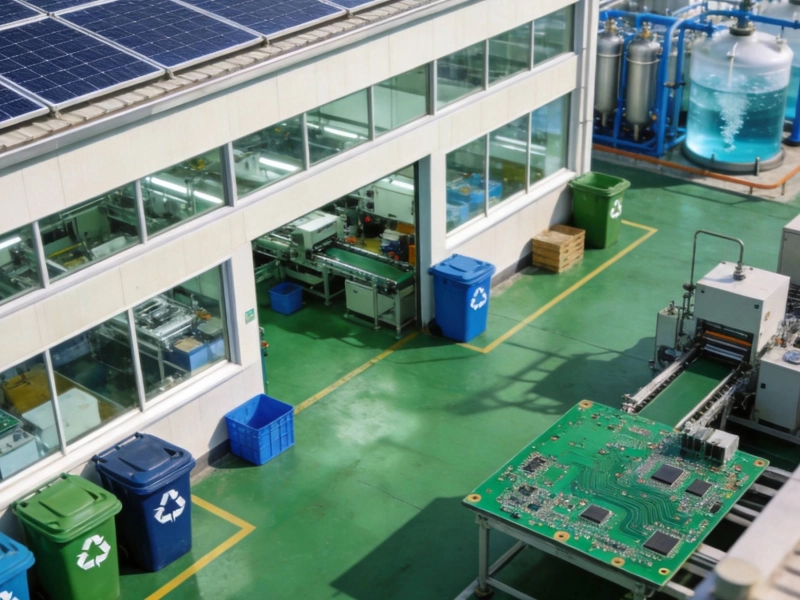
Environmental Standards in China: How PCB Factories are Going GreenSeptember/11/2026

Common Pitfalls in Custom PCB Fabrication and How to Avoid ThemAugust/07/2026

From Prototype to Mass Production: Scaling Your Custom PCB Project SeamlesslyJuly/07/2026
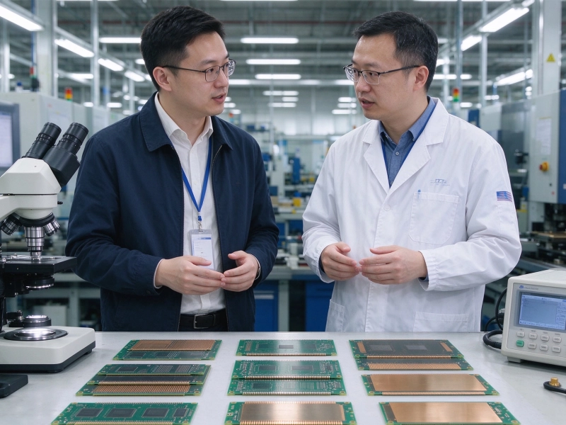
How to Choose the Right PCB Fabrication Manufacturer for Your StartupOctober/14/2026
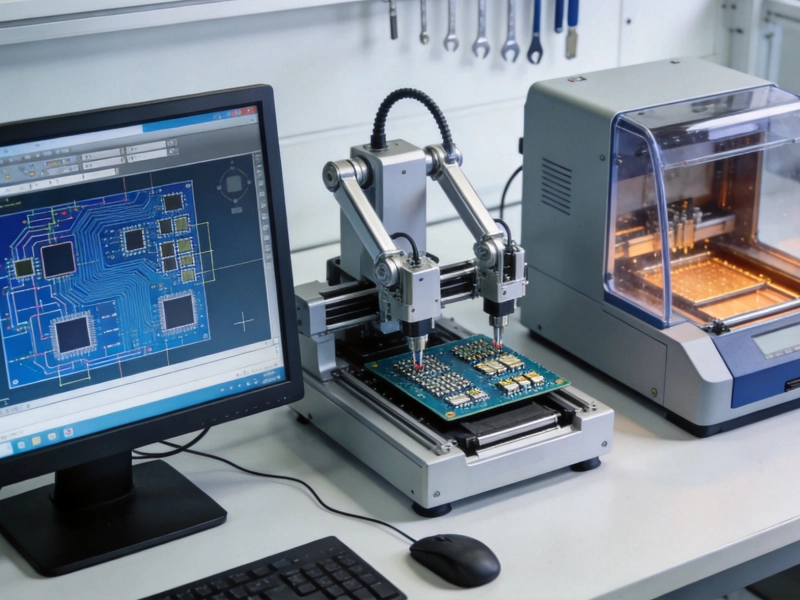
The Role of DFM (Design for Manufacturability) in Custom Board SuccessSeptember/02/2026
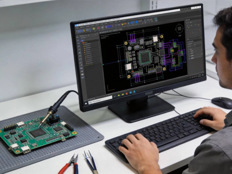
Essential Tips for Your First Custom PCB OrderJune/02/2026

The Economics of Customization: Balancing Performance and Budget in PCB DesignJune/17/2026