Open Nav

The modern electronics industry increasingly demands boards that combine multiple assembly technologies to achieve optimal performance, cost, and reliability. Mixed technology Pcb Assembly, which integrates Surface Mount Technology (SMT), through-hole technology (THT), and odd-form components on a single board, has become a standard approach rather than an exception. This integration presents unique challenges that require careful planning, specialized processes, and deep understanding of how different component types interact within the assembly workflow.
Each assembly technology brings distinct advantages that make it suitable for specific applications. SMT excels at miniaturization and high-density assembly. THT provides superior mechanical robustness for connectors and components subject to physical stress. Odd-form components serve specialized purposes that neither SMT nor THT can adequately address. The art of mixed technology assembly lies in intelligently combining these technologies to leverage their respective strengths while minimizing the complexity and cost of the overall assembly process.
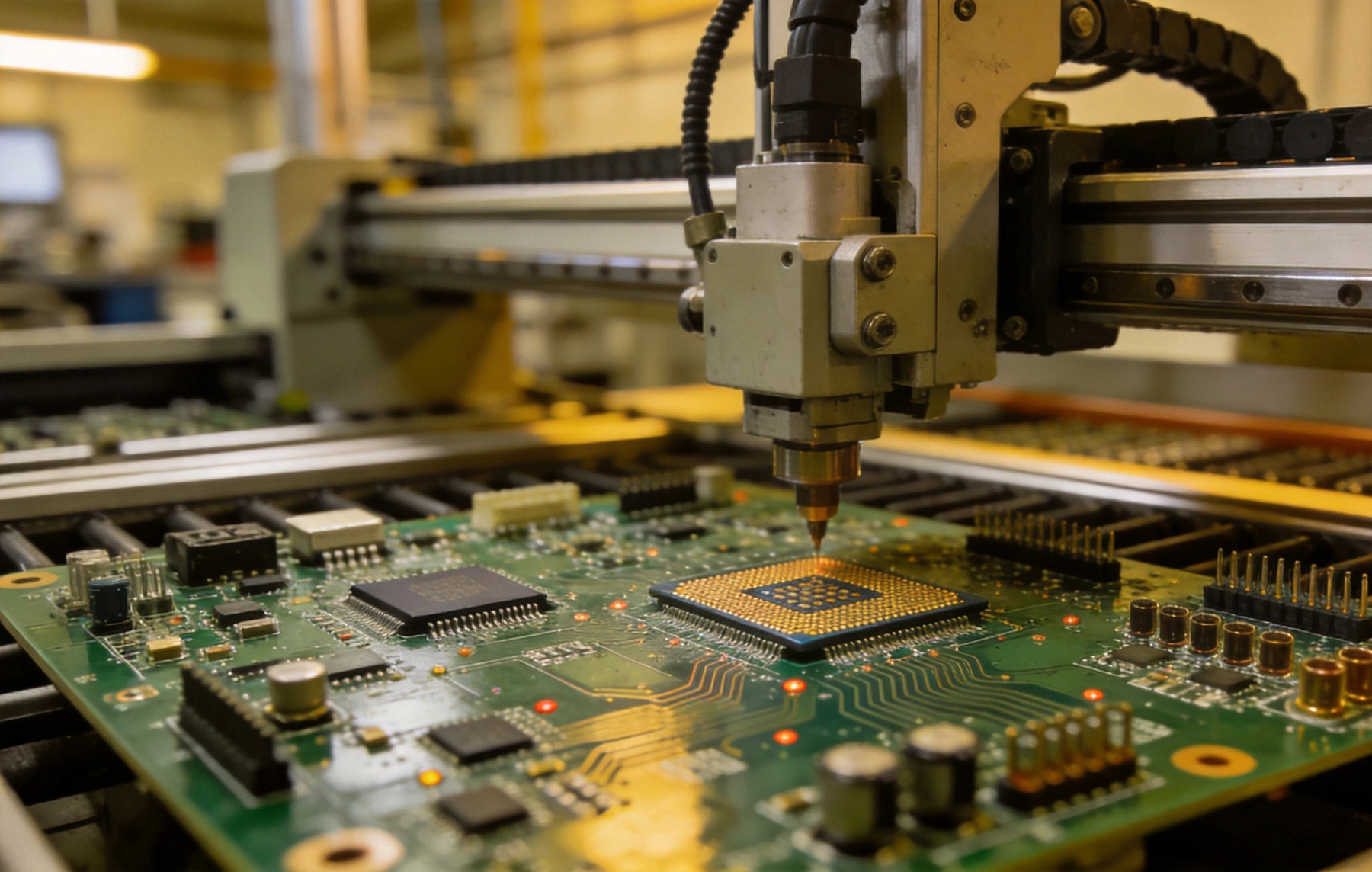
Surface Mount Technology dominates modern Pcb Assembly due to its ability to place components with high speed, precision, and density. SMT components are soldered directly to pads on the board surface without leads passing through holes. This technology enables miniaturization, supports automated placement at high speeds, and generally provides excellent electrical performance due to shorter lead lengths. However, SMT components typically cannot withstand high mechanical stress and may have limitations for certain connector types or high-power applications.
Through-hole technology remains essential for components requiring superior mechanical attachment or that must withstand repeated stress cycles. THT components feature leads that pass through plated holes in the PCB and are soldered on the opposite side, creating a robust mechanical connection that resists vibration, thermal cycling, and physical handling stress. Connectors, transformers, large electrolytic capacitors, and components subject to wire termination or field service typically require through-hole mounting. The trade-off is lower assembly speed and reduced component density compared to SMT.
Odd-form components encompass everything outside standard SMT and THT categories. These include large transformers and inductors with custom shapes, heavy connectors, battery holders, heat sinks, shielded enclosures, and components with unusual lead configurations. Odd-form components often require custom handling, specialized fixtures, or manual assembly operations. They represent both the greatest challenge and the greatest flexibility in mixed technology assembly, enabling designs that would otherwise be impossible with standard component packages.
Mixed technology assembly often provides the optimal balance between performance, reliability, and cost for complex electronic products. A well-designed mixed-technology board uses SMT for the majority of components where density and speed matter, THT for mechanical-critical connections, and odd-form components where specialized requirements demand them. This selective application of different technologies typically produces better results than attempting to force everything into a single assembly method.
The cost implications of mixed technology assembly extend beyond simple component costs. SMT offers the lowest assembly cost per placement for standard components, but this advantage diminishes when SMT is forced to handle components better suited to through-hole mounting. Conversely, using THT exclusively would dramatically increase assembly costs and reduce board density. The economic sweet spot often lies in thoughtful mixed technology that applies each method where it provides the greatest value.
Supply Chain considerations also favor mixed technology approaches in many applications. The electronics industry continues to experience component shortages and long lead times, and mixed technology designs often provide greater flexibility when certain components become unavailable. A design that can accept both SMT and THT versions of a component, or that can substitute an odd-form solution when a standard package is unavailable, demonstrates greater resilience to Supply Chain disruptions.
Successful mixed technology assembly requires meticulous process planning that accounts for the interactions between different assembly methods. The sequence in which technologies are applied significantly impacts quality, efficiency, and defect rates. Planning must consider solder compatibility, thermal profiles, handling requirements, and inspection methods for each technology type. Getting the process sequence wrong can result in damaged components, solder defects, or complete assembly failure.
The most common process sequence applies SMT first, followed by THT and odd-form components. This ordering takes advantage of SMT's sensitivity to handling and contamination while the board surface is clean and undamaged. THT and odd-form assembly typically involves more manual handling and potential for board stress, making it appropriate after the delicate SMT operations are complete. Additionally, SMT components are generally rated for higher reflow temperatures than wave soldering temperatures, allowing THT components to be added in a subsequent wave soldering step.
However, alternative sequences may be necessary depending on specific component requirements. Some odd-form components cannot tolerate the thermal profiles used for Smt Assembly, requiring them to be placed before reflow processing. Others may be too tall or positioned in ways that interfere with SMT pick-and-place operations, requiring them to be added after Smt Assembly is complete. Careful analysis of each component's thermal and handling requirements determines the optimal assembly sequence.
Mixed technology assembly lines require equipment capable of handling the diverse requirements of different component types. SMT lines feature pick-and-place machines, solder paste printers, and reflow ovens optimized for Surface Mount components. THT assembly typically requires wave solder machines or selective solder systems, often combined with through-hole insertion equipment ranging from manual placement stations to automated radial and axial component inserters.
Odd-form component handling presents the greatest equipment diversity challenges. Some odd-form components can be handled by modified SMT equipment with specialized nozzles and feeders. Others require custom fixture development for automated processing. Many odd-form components, particularly those with unusual shapes or that are large and heavy, must be placed manually despite the efficiency costs. Deciding which odd-form components justify custom Automation investment versus manual assembly is an important economic consideration.
Inspection and testing equipment must also address the requirements of all technologies present on the board. SMT inspection typically employs automated optical inspection (Aoi) and X-ray Inspection for hidden joints. THT inspection may require different Aoi angles or manual inspection for joints hidden by component bodies. Odd-form components often require custom inspection approaches or Functional Testing to verify proper placement and connection. Planning inspection coverage across all technologies ensures consistent Quality Assurance.
Design decisions made early in the Product Development process have outsized impact on mixed technology assembly success. Boards designed with assembly considerations in mind are substantially easier and more cost-effective to produce than those designed primarily for electrical performance without attention to manufacturing requirements. Collaboration between design engineers and manufacturing specialists during the design phase prevents costly redesigns and production problems.
Component placement rules must account for the requirements of all assembly technologies present. SMT components benefit from systematic placement that maximizes pick-and-place efficiency. THT components must be positioned to allow proper through-hole insertion without interference. Odd-form components require adequate clearance for manual handling or custom Automation. Creating clear placement zones for each technology type simplifies assembly planning and reduces the risk of component damage or placement errors.
Thermal Management considerations differ between assembly technologies and must be addressed in design. SMT components experience the thermal profile of reflow soldering, which subjects all components to similar peak temperatures. THT wave soldering exposes the board to higher temperatures than reflow but for shorter durations. Odd-form components may require hand soldering with yet different thermal profiles. Component selection and placement must consider these varying thermal exposures to prevent damage.
Pad design for mixed technology boards must accommodate the specific requirements of each assembly method. SMT pads follow standard Design Rules for the specific component packages being used, with attention to solder paste volume requirements and thermal balance. THT pads must provide adequate annular ring for the drilling and plating processes, with pad sizes appropriate for the expected hole diameters and any reinforced plating requirements for high-current applications.
Hybrid pad designs that serve both SMT and THT functions require careful consideration. Some designs place SMT components adjacent to through-holes in ways that share pad geometry. This optimization can save board space but requires careful analysis of solder flow during wave or selective soldering to prevent unintended solder bridging or insufficient joints. Generally, keeping SMT and THT pad areas clearly separated reduces assembly complexity and defect risk.
Odd-form component mounting often requires custom pad or termination designs specific to the component geometry. These may include specialized holes, slots, or surface features that engage with the component's unique mounting provisions. Early coordination with odd-form component suppliers ensures that mounting designs accommodate both the component requirements and the assembly process capabilities.
Soldering in mixed technology assembly requires multiple processes tailored to the requirements of different component types. The reflow process handles all SMT components simultaneously, applying solder paste to pads, placing components, and creating solder joints through a controlled thermal profile. This process must be optimized for the specific solder alloy, board characteristics, and component thermal tolerances present in the assembly.
Through-hole components can be soldered using several methods depending on volume requirements and board characteristics. Wave soldering passes the entire board, with components already inserted, over a standing wave of molten solder that fills holes and creates joints on the solder side. This process is fast and cost-effective for high-volume production but can expose SMT components to thermal shock and may not provide adequate solder fill for all hole geometries. Selective soldering targets specific through-hole joints with localized solder application, avoiding exposure of sensitive SMT components to unnecessary thermal stress.
Hand soldering remains essential for odd-form components and for rework situations. Skilled operators can handle components with unusual geometries, make repairs, and address assembly issues that automated processes cannot handle. However, hand soldering introduces variability and relies on operator skill, making it important for processes to include appropriate Quality Control measures such as inspection checklists and periodic verification.
Thermal profile management becomes increasingly complex as additional assembly technologies are introduced. The SMT reflow profile must accommodate all Surface Mount components while not exceeding the thermal limits of any component or the board substrate. This requires careful analysis of the thermal sensitivity of each component, often expressed as peak temperature and time above liquidus requirements for the chosen solder alloy.
When through-hole components are added after reflow, the thermal profile of wave or selective soldering must be considered separately. Wave soldering profiles are typically shorter in duration but reach higher peak temperatures than reflow soldering. Components must be rated for wave soldering exposure if they will be on the board during that process. Components that cannot tolerate wave soldering must be added in a subsequent process step.
For assemblies with odd-form components requiring hand soldering or specialized processes, Thermal Management focuses on local heat application rather than whole-board thermal profiles. These components often have high thermal mass or temperature-sensitive elements that make whole-board thermal processing impractical. Planning for localized heating minimizes stress on surrounding components and board materials.
Quality Control in mixed technology assembly requires inspection and testing strategies appropriate for each technology type and their interactions. A comprehensive quality approach addresses component placement accuracy, solder joint formation, potential defects unique to each assembly method, and overall board functionality. The complexity of mixed technology assembly makes thorough quality control essential for maintaining acceptable defect rates.
Automated optical inspection provides rapid, consistent inspection of solder joints and component placement for visible features. AOI systems can detect many common defects including missing components, misaligned placements, insufficient or excessive solder, and bridged connections. However, AOI has limitations for hidden joints such as BGA solder connections and may require supplementary inspection methods for complete coverage.
X-ray Inspection addresses the inspection limitations for hidden joints that AOI cannot adequately evaluate. BGA packages, QFN packages with hidden thermal pads, and multilayer connections require X-ray inspection to verify proper solder formation. In mixed technology assemblies with complex SMT components, X-ray inspection becomes even more critical for ensuring joint quality that cannot be visually confirmed.
Functional Testing validates that the assembled board performs as intended, regardless of the visual appearance of individual solder joints. Functional test programs apply power and signals to the board, verifying that each circuit node behaves correctly. This approach catches defects that may escape visual inspection, including marginal solder joints that make initial electrical contact but may fail under stress or over time.
In-circuit testing probes test points on the board to verify component presence, orientation, and basic functionality. Ict fixtures must accommodate the varied component heights and geometries present in mixed technology assemblies, which can be more challenging than pure SMT boards. The presence of through-hole components may simplify some aspects of Ict probing while complicating others through reduced access to probe points.
Burn-in and environmental stress testing expose boards to elevated temperature, voltage, or mechanical stress to accelerate failure of marginal units. These tests are particularly valuable for mixed technology assemblies where thermal cycling can expose weaknesses in solder joints of any type. The investment in stress testing often proves worthwhile for applications where field reliability is critical.
Component interference represents one of the most frequent challenges in mixed technology assembly. Through-hole components with tall bodies can block access for SMT placement heads, or their leads can interfere with surface routing. Similarly, odd-form components may require clearances that conflict with SMT component placement areas. Early design review identifying potential interference issues enables design modifications before they become production problems.
Solder splash and spatter from wave soldering can contaminate surface mount areas, creating potential reliability issues or assembly problems for subsequent processes. Proper board design that positions wave-soldered areas away from critical SMT regions, combined with appropriate flux management and solder wave configuration, minimizes this contamination risk. Post-wave cleaning removes any contamination that does occur.
Thermal stress during multiple soldering operations can degrade sensitive components or board materials. Components that will survive multiple thermal cycles must be selected accordingly, and process sequences must minimize unnecessary thermal exposure. Careful process control and verification that actual thermal profiles remain within component specifications ensures that multiple soldering operations do not compromise product reliability.
Managing the supply chain for mixed technology assemblies introduces additional complexity compared to pure SMT or THT boards. Different component types often come from different suppliers, have different lead times, and may have different availability characteristics. Coordinating deliveries to ensure all components are available when needed for assembly requires more sophisticated planning than single-technology assemblies.
Component handling and storage requirements vary between technologies. SMT components in tape-and-reel or tray packaging have specific moisture sensitivity level requirements that must be tracked and managed. Through-hole components may have different storage requirements. Odd-form components often require special handling or storage that differs from both SMT and standard THT components. A comprehensive component management system addresses these varied requirements.
Obsolescence management becomes more complex when designs depend on multiple technology types. A component that becomes unavailable may require re-engineering of not just the replacement component but potentially the entire assembly approach. Designing flexibility into mixed technology assemblies, such as accommodating alternative component packages or assembly methods, provides insurance against obsolescence disruptions.
Establish clear Design Rules that address all assembly technologies from the beginning of Product Development. These rules should specify acceptable component packages for each technology type, placement constraints, thermal requirements, and any technology-specific design guidelines. Following consistent rules across products simplifies assembly planning and reduces the learning curve for new designs.
Maintain open communication between design, manufacturing, and test engineering throughout product development. The insights gained from manufacturing experience often identify design improvements that reduce cost or improve quality without impacting electrical performance. This collaboration is particularly valuable in mixed technology assembly where design decisions in one area can significantly impact assembly processes in others.
Invest in process documentation that captures the unique requirements of each mixed technology assembly. Standard work instructions should address technology-specific handling, placement, and soldering requirements. Training materials should ensure that all personnel understand not just their specific tasks but how their work fits into the overall assembly process. Knowledge preservation reduces variability and supports continuous improvement.
Cost optimization in mixed technology assembly requires balancing trade-offs between different assembly methods. While SMT offers the lowest per-placement cost, using it inappropriately for components better suited to THT may increase total cost through higher defect rates, reduced reliability, or both. Analysis of the true cost of each assembly method, including defect costs and reliability implications, guides optimal technology selection.
Automation investment should focus on the highest-volume operations where automation provides the greatest return. SMT placement is almost universally automated due to its high speed and precision. Through-hole insertion for standard components is often automated for high volumes but may be manual for lower volumes or unusual packages. Odd-form components frequently require custom automation or manual assembly depending on volume and geometry.
Design For Manufacturability reviews can identify opportunities to reduce assembly cost without compromising performance. Simplifying odd-form component requirements, standardizing hole sizes and pad geometries, and minimizing mixed-technology interface complexity all contribute to more cost-effective assembly. These optimizations are most valuable when identified early in design, making Dfm Review a critical step in mixed technology product development.
Q: What is the typical assembly sequence for mixed SMT and THT boards?
A: The most common sequence places SMT components first, then inserts and solders THT components in a subsequent operation. This ordering protects delicate SMT components during the more handling-intensive THT assembly process and allows wave or selective soldering to attach through-hole components without exposing SMT joints to unnecessary thermal stress. Alternative sequences may be necessary depending on specific component thermal requirements.
Q: Can all SMT components survive wave soldering?
A: No, not all SMT components are rated for wave soldering exposure. Components with plastic bodies or those containing temperature-sensitive elements may be damaged by the higher temperatures of wave soldering. These components must be placed after wave soldering using selective soldering or hand soldering. Always verify component temperature ratings before including them in wave soldering operations.
Q: How do you handle odd-form components in high-volume production?
A: High-volume odd-form component handling typically requires custom automation solutions including specialized feeders, grippers, and placement systems. The economic justification for this automation depends on volume and the cost differential versus manual assembly. For some odd-form components, partnering with specialized contract manufacturers who have existing automation for specific component types may be more cost-effective than developing custom automation.
Q: What inspection methods are needed for mixed technology assemblies?
A: Mixed technology assemblies typically require multiple inspection approaches. Automated optical inspection covers visible solder joints and component placement. X-ray inspection addresses hidden joints in BGA, QFN, and multilayer areas. Manual inspection may be needed for odd-form components or areas inaccessible to automated systems. Functional and in-circuit testing verify overall assembly quality and performance.
Q: How do thermal profiles differ between SMT and THT soldering?
A: SMT reflow soldering uses controlled thermal profiles that gradually heat the entire assembly to solder melting temperature, typically peaking around 245-260°C depending on solder alloy. Wave soldering exposes the board bottom to solder at approximately 260-280°C for shorter durations. Selective soldering applies localized heat to specific joints. Each process requires components and boards rated for the specific thermal exposure.
Mixed technology PCB assembly represents both an opportunity and a challenge for electronics manufacturers. When executed well, it enables products that combine the density and cost advantages of SMT, the mechanical robustness of THT, and the flexibility of odd-form components. The result can be a product that performs better, costs less, and lasts longer than would be possible with a single assembly technology.
Success in mixed technology assembly requires attention to the unique requirements of each technology while managing their interactions within the overall process. Design practices that consider assembly from the beginning, process planning that accounts for technology-specific requirements, and quality control that addresses all assembly methods contribute to successful outcomes. The investment in these practices pays returns through reduced defects, improved reliability, and more cost-effective production.
As electronic products continue to increase in complexity while demanding greater reliability and lower cost, mixed technology assembly will remain an essential capability for manufacturers serving demanding applications. Companies that master the challenges of integrating SMT, THT, and odd-form components position themselves to compete effectively across diverse market segments from consumer electronics to industrial controls to automotive systems.
SMT vs THT PCB Assembly in China: Which Technology is Right for Your Project?June/10/2026
How Chinese Manufacturers Ensure Precision in the SMT PCB Assembly ProcessJune/03/2026
Inspection Standards: IPC-A-610 and What it Means for Your Assembled BoardsAugust/03/2026

The Importance of BOM Accuracy in the PCB Assembly ProcessJuly/13/2026

Prototyping vs. Production Assembly: Different Approaches for Different StagesSeptember/08/2026
Common Defects in PCB Assembly and How Manufacturers Prevent ThemSeptember/18/2026

Managing Cost and Quality in Quick Turn PCBsJune/04/2026
The Benefits of Combining PCB Fabrication and AssemblyMay/22/2026