
RF and Microwave Pcb applications demand materials that maintain consistent electrical performance at frequencies where standard FR4 falls short. When designing circuits for 5G communications, automotive radar, satellite systems, or test equipment, the choice of high-frequency substrate directly determines whether the design achieves its performance targets. Understanding how to assess high-frequency material capabilities helps engineers select substrates that balance electrical performance, manufacturing compatibility, and cost for their specific applications. This article provides the framework for evaluating high-frequency materials across the parameters that matter most for RF and microwave designs.
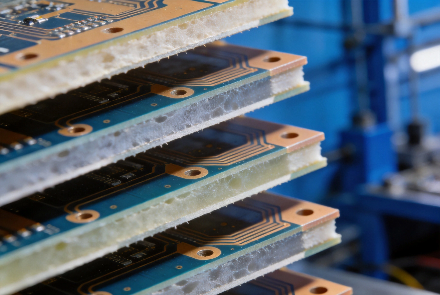
The Dielectric Constant, also called relative permittivity or Dk, describes how the substrate material affects the capacitance of a transmission line compared to air. When electromagnetic waves propagate through a PCB trace, they interact with the dielectric material surrounding the conductor. Higher dielectric constants concentrate the electric field within the material, increasing capacitance and reducing the velocity of propagation. For RF designs, Dielectric Constant stability across frequency and temperature directly impacts whether impedance targets can be met consistently in production.
Most high-frequency applications target dielectric constants between 2.1 and 12, compared to approximately 4.5 for standard FR4. Lower dielectric constants provide advantages for microwave applications where signal velocity and low loss matter most. Higher dielectric constants enable smaller circuit dimensions at a given frequency because wavelengths shrink as the propagation velocity decreases. Designers choose dielectric constants based on their specific tradeoffs between wavelength, physical dimensions, and loss requirements.
The variation of dielectric constant with frequency, called dispersion, affects wideband applications. Some materials maintain nearly constant Dk across wide frequency ranges, while others exhibit significant variation. For frequency-hopping or wideband systems, materials with stable Dk prevent impedance shifts that would require compensation across the operating band. Datasheets typically specify Dk at specific frequencies, and understanding these measurement conditions helps interpret the values correctly.
The Loss Tangent, also called dissipation factor or Df, quantifies how much energy the dielectric material absorbs as electromagnetic waves propagate through it. Lower loss tangents indicate materials that dissipate less signal energy as heat. At microwave frequencies, even small differences in Loss Tangent create significant signal attenuation over practical trace lengths. A material with Df of 0.001 absorbs ten times less energy than one with Df of 0.01 at the same frequency.
Signal loss in PCB traces comes from both dielectric losses and conductor losses. Conductor losses depend on copper roughness and conductivity, while dielectric losses depend on the substrate material. At frequencies above 10 GHz, dielectric losses often dominate the total attenuation budget. For long interconnects in phased array radar or high-speed digital links, minimizing dielectric loss directly improves system performance and reduces power requirements for drivers.
Comparing loss tangent values requires attention to measurement frequency because Df varies with frequency. Materials rated for 10 GHz may show different loss characteristics at 30 GHz or 77 GHz. Look for datasheet values at frequencies matching your application, or request characterization data for the specific frequencies where your design operates. Some manufacturers provide loss tangent curves showing performance across wide frequency ranges.
The glass transition temperature, or Tg, indicates the temperature at which the material transitions from a rigid glassy state to a softer rubbery state. Operating PCBs above Tg risks dimensional instability, impaired electrical performance, and potential delamination. High-frequency materials typically offer Tg values ranging from 280 degrees Celsius for standard ceramics to over 300 degrees Celsius for advanced hydrocarbon composites.
For applications involving lead-free soldering or high-power dissipation, thermal margin above expected operating temperatures becomes critical. A material with Tg of 280 degrees Celsius provides less margin when operated at 200 degrees Celsius than one with Tg of 350 degrees Celsius, even if both specifications seem adequate at first glance. Engineers should account for temperature gradients within assemblies when evaluating thermal margins.
Thermal conductivity determines how effectively heat flows through the substrate away from hot components. Standard Pcb Materials offer thermal conductivity around 0.3 watts per meter-Kelvin, which limits heat spreading through the board itself. For power amplifier circuits or other high-dissipation components, this limited conductivity may require external heatsinking or metal-core substrates.
Some high-frequency materials incorporate ceramic fillers that improve thermal conductivity while maintaining favorable electrical properties. These enhanced materials can achieve thermal conductivity of 0.5 to 1.0 W/mK, providing moderate heat spreading without the electrical losses of metal core constructions. For applications requiring both RF performance and Thermal Management, these materials offer compromise solutions that pure dielectrics cannot match.
The coefficient of thermal expansion, or CTE, describes how dimensions change with temperature. When CTE of the dielectric differs significantly from copper or component terminations, thermal cycling creates mechanical stress that can crack solder joints or delaminate layers. This concern becomes more significant for assemblies undergoing repeated temperature extremes.
High-frequency materials based on ceramic fillers typically offer CTE values between 6 and 12 parts per million per degree Celsius, reasonably matching the 17 ppm/C of copper. Pure polymer materials may show higher CTE values around 50 to 60 ppm/C, creating larger thermal expansion mismatches. Understanding CTE helps predict reliability performance in applications subject to thermal cycling.
High-frequency materials vary significantly in their tendency to absorb moisture from the environment. Moisture absorption affects dimensional stability, electrical properties, and processability. Some materials absorb less than 0.1 percent moisture by weight, while others may absorb 0.5 percent or more. For assemblies operating in humid environments or undergoing moisture-sensitive assembly processes, low moisture absorption becomes important.
Moisture absorbed during storage can vaporize during soldering reflow, creating pressure that blisters or delaminates the board. Materials with high moisture absorption require bake-out procedures before assembly to prevent pop-corning failures. Understanding moisture sensitivity helps plan appropriate handling and storage procedures for each material type.
The bond between copper foil and high-frequency dielectric material affects both reliability and electrical performance at high frequencies. Some materials use proprietary surface treatments to enhance copper adhesion without degrading electrical properties. Others rely on mechanical roughening that may increase losses at microwave frequencies.
When evaluating materials, consider the recommended surface preparation procedures and how they affect electrical performance. Low-profile copper foils with smoother surfaces reduce conductor losses at high frequencies but may compromise adhesion if the material surface treatment is not optimized. Manufacturer recommendations balance these tradeoffs based on their formulation expertise.
High-frequency materials differ significantly in how readily they process through standard PCB Fabrication operations. Some materials behave similarly to FR4 and can use conventional drilling, plating, and lamination equipment. Others require specialized processes that increase manufacturing complexity and cost. Understanding these differences helps set realistic expectations for Prototype and production lead times.
Rogers hydrocarbon materials, for example, require modified desmear processes before plating because laser roughening produces different surface characteristics than chemical treatments used for FR4. Taconic materials based on PTFE require plasma treatment rather than chemical desmear due to the chemical inertness of fluoropolymers. These process differences affect which manufacturers can efficiently produce boards from each material.
Rogers leads the high-frequency PCB market with materials spanning a wide range of dielectric constants and performance levels. RO4000 series hydrocarbon composites offer dielectric constants from 3.4 to 6.15 with low loss tangents around 0.003 at 10 GHz. These materials process similarly to FR4, enabling use of standard manufacturing equipment with modified parameters.
RO3000 series ceramic-filled PTFE materials provide dielectric constants from 3.0 to 10.2 with loss tangents below 0.001. The ceramic filler improves dimensional stability and thermal conductivity while PTFE provides excellent electrical performance. However, PTFE materials require specialized processing including plasma desmear and unique lamination procedures.
Taconic offers a comprehensive portfolio of high-frequency materials including their TLY, RF, and TLX series. TLY materials provide dielectric constants around 2.2 with loss tangents of 0.0009 at 10 GHz, positioning them for applications where lowest loss is paramount. Their PTFE-based formulations require similar processing to Rogers PTFE materials.
Taconic's lower-cost options like the TLX series target price-sensitive applications where adequate performance at moderate frequencies meets requirements. These materials provide cost-effective solutions for consumer wireless and industrial applications where extreme performance is not required.
Isola enters the high-frequency market with their ITERGY and Astra families, targeting applications from 5G infrastructure to automotive radar. Their materials emphasize balance between electrical performance, Thermal Management, and manufacturing compatibility. Isola's global manufacturing presence provides Supply Chain advantages for multinational programs.
Chinese manufacturers including Shengyi and Huapin offer high-frequency materials at lower price points than Western alternatives. Performance specifications approach international competitors, though long-term reliability data may be less extensive. These materials suit cost-sensitive applications where absolute performance margins allow for broader material selection.
5G base station equipment operating at 28 GHz and above demands materials with exceptional loss characteristics at frequencies where propagation losses are inherently higher. The wide bandwidths of 5G signals also require stable dielectric properties across frequency. Rogers RO3000 series or equivalent materials from competitors typically serve these applications, with dielectric constants around 3.0 providing good balance of size and performance.
For active antenna systems with power amplifiers and beamforming networks, thermal conductivity becomes as important as electrical performance. Materials incorporating thermal vias and metal backing provide heat spreading that protects semiconductor devices from overheating. The interaction between electrical and thermal requirements drives material selection toward solutions optimized for both.
Automotive radar operating at 77 GHz presents extreme challenges for Pcb Materials. At these frequencies, even small loss differences create measurable range and sensitivity variations. Rogers RO3003 or equivalent materials with Df below 0.001 are typically specified. Dielectric constant must remain stable across the temperature extremes encountered in automotive environments.
The antenna feed network and mixer circuits in radar modules require precise Impedance Control at frequencies where manufacturing tolerances become significant relative to wavelength. Material consistency from lot to lot directly impacts production yields. Designers working on automotive radar often qualify specific material lots to ensure predictable performance across production quantities.
Space applications prioritize radiation tolerance in addition to electrical performance. Some high-frequency materials incorporate additives that resist radiation-induced property changes. Total dose effects from cosmic radiation can degrade standard materials over orbital lifetimes, while radiation-tolerant formulations maintain performance.
Thermal cycling between sunlight and shadow creates severe stress on materials used in satellite applications. Low outgassing materials prevent contamination of optical surfaces and sensors. Multi-layer insulation and thermal considerations drive material selection toward combinations that can withstand thousands of thermal cycles without delamination or property changes.
Leading high-frequency material vendors provide extensive technical support that accelerates design implementation. Rogers offers microwave office and other CAD library files that simplify impedance calculations. Design guides and application notes address common challenges like via transitions and ground plane management. This support infrastructure helps engineers avoid pitfalls that would require design iterations.
Evaluate vendor technical support when selecting materials for critical applications. The quality of application engineering assistance varies significantly between manufacturers. For challenging designs, vendors who provide responsive technical support deliver value beyond the material specification itself.
High-frequency materials often have longer supply lead times than standard FR4 due to smaller production volumes and more specialized manufacturing. Material shortages can halt production just as severely as component shortages. Understanding vendor inventory policies and production lead times helps plan procurement to prevent supply disruptions.
Some programs qualify alternate materials to provide backup supply options. However, material changes require revalidation that adds cost and schedule risk. When possible, securing multi-quarter material coverage reduces Supply Chain vulnerability. Long-term agreements with vendors can secure allocation during tight supply periods.
What is the most important property for high-frequency Pcb Material Selection?
The most critical property depends on your application. For long interconnects in phased array systems, loss tangent becomes paramount because signal attenuation directly impacts system performance. For narrowband applications like filters, dielectric constant stability matters more because impedance matching depends on predictable properties. Evaluate your specific performance drivers before prioritizing material properties.
How do I choose between PTFE and hydrocarbon-based materials?
PTFE materials like Rogers RO3000 series offer the lowest loss but require specialized processing that increases manufacturing cost and complexity. Hydrocarbon materials like Rogers RO4000 series provide lower loss than FR4 while processing on standard equipment with modified parameters. For frequencies above 30 GHz, PTFE materials typically justify their cost premium. Below 20 GHz, hydrocarbon materials often provide adequate performance with better manufacturing compatibility.
What dielectric constant should I choose for my application?
Lower dielectric constants around 2.2 to 3.0 suit microwave and millimeter-wave applications where minimum loss and maximum signal velocity matter. Mid-range dielectric constants around 3.5 to 6.0 provide balance for mixed-signal applications. Higher dielectric constants around 10 to 12 suit applications where physical size reduction is paramount and loss is less critical. Match dielectric constant to your dimensional and loss requirements.
How do I verify material performance in production?
Request test coupons from your fabricator that use the same material and processing as your production boards. Impedance testing on these coupons verifies that actual performance matches design calculations. For critical applications, material certificates of conformance provide traceability to specific material lots. Statistical process control on impedance data over production runs confirms consistent performance.
Can I use standard FR4 for high-frequency applications?
FR4 can work adequately for applications below 1 GHz where loss is not critical and impedance tolerances are loose. Above 5 GHz, FR4 loss becomes prohibitive for most applications. The high loss tangent of FR4 causes excessive signal attenuation, and its dielectric constant variation with frequency complicates wideband designs. For applications above 5 GHz, dedicated high-frequency materials are typically necessary.
Assessing high-frequency material capabilities requires understanding how electrical, thermal, and mechanical properties interact with your specific application requirements. The material parameters that matter most—dielectric constant, loss tangent, thermal properties, and processability—must be evaluated together rather than in isolation. Tradeoffs between performance, cost, and manufacturing complexity drive material selection decisions.
The leading high-frequency material manufacturers each offer product families optimized for different application segments. Rogers, Taconic, Isola, and regional manufacturers provide options spanning the performance-cost spectrum. Understanding these options enables informed selection that balances technical requirements with business constraints.
Building relationships with material vendors and their authorized distributors provides access to technical support and supply continuity that benefits long-term programs. Early engagement with material experts during design development prevents costly material-related redesigns later. The investment in thorough material assessment pays returns through designs that achieve their performance targets and production that delivers consistent results.
Heavy Copper PCBs: Capabilities for High-Current and Power ElectronicsJuly/14/2026
Minimum Trace and Space: How Far Has PCB Technology Advanced?July/01/2026
Large Format vs. Miniature PCBs: Evaluating Size Constraints and CapacitiesAugust/14/2026
Any-Layer Interconnect: The Pinnacle of High-Density PCB TechnologyJuly/10/2026
Decoding the Spec Sheet: Understanding a Factory's PCB Fabrication CapabilitiesJune/11/2026
Top Trends Shaping the Chinese PCB Manufacturing Industry in 2026May/21/2026
Why Global Brands Are Turning to PCB Fabrication in China in 2026May/21/2026
High-Frequency Materials: Assessing Capabilities for RF and Microwave PCBsJuly/23/2026