Open Nav

Every electronic product begins with a Prototype and ends with a manufactured product, but the journey between those two points requires entirely different approaches, mindsets, and partner relationships. Treating production assembly like an oversized prototyping exercise, or expecting Prototype-level flexibility from a high-volume manufacturer, is one of the most common and costly mistakes in Hardware Development. Understanding the structural differences between these two stages prevents misaligned expectations, prevents wasted budget, and ultimately gets better products to market faster.
The fundamental distinction is one of purpose. Prototyping exists to answer questions. Production assembly exists to execute a proven design reliably at scale. The metrics that matter in each stage are different, the tolerances for cost and schedule are different, and the technical capabilities required from a manufacturing partner are different. This article examines those differences across the full scope of Pcb Assembly, from design preparation through final test.
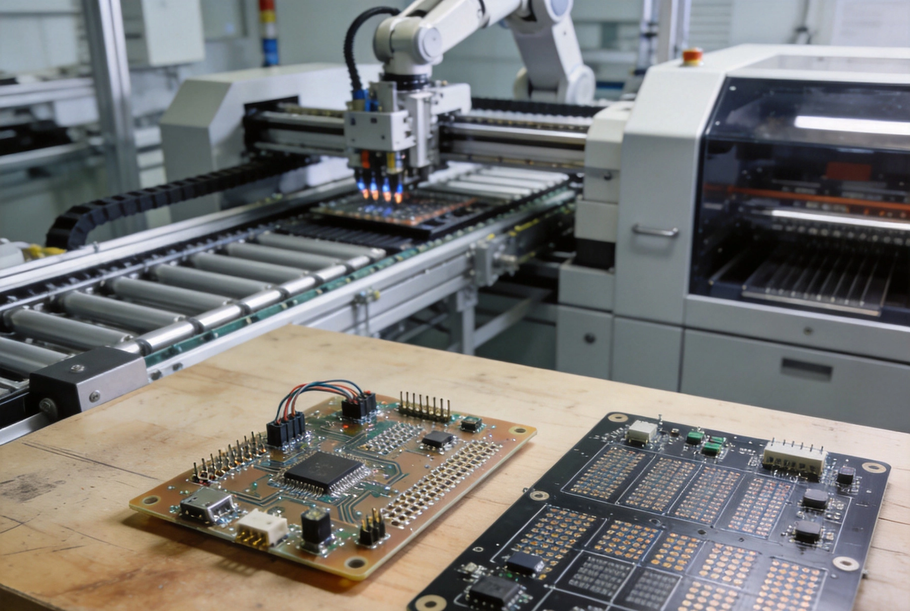
A prototype's primary job is to validate or invalidate a design assumption as quickly as possible. The prototype exists to answer questions: Does this circuit work? Does this thermal design hold under load? Do the components fit the footprint? Does the firmware talk to the hardware correctly? Each question is high-stakes, but the tolerance for cost per board is high and the tolerance for schedule delay is very low. Speed justifies almost any trade-off.
In the prototyping phase, design changes arrive frequently and without notice. A single prototype run may uncover a pinout error that requires a board spin before the next test. Firmware development may lag hardware by weeks, making it pointless to assemble all components on the first spin. Components may not yet be finalized, with the team evaluating three competing voltage regulators that all have different footprints. The assembly process must accommodate these realities without friction.
Quick-turn assembly services are purpose-built for this phase. These services accept design files with minimal documentation, assemble partial boards, use whatever components are available in stock, and deliver within days rather than weeks. The trade-off is higher per-board cost, looser tolerances on fine-pitch components, and limited documentation of the assembly process. For a prototype that will be tested once and then redesigned, these trade-offs are entirely acceptable.
Even at the prototype stage, the board layout should be designed with manufacturing in mind, though the priorities differ from production. In prototyping, test access takes precedence over routing density. The engineer will need to probe signals with oscilloscope leads, inject test signals at specific nodes, and measure voltages at test points that may not be on the final board. Designing test points, adding probe pad access, and routing critical signals to accessible locations on the prototype board can save days of debugging time later.
Component selection for prototypes should be guided by final production intent. Sourcing challenges that can be worked around during prototyping (hand-soldering a QFN, bodge-wiring a missing component) will become fatal in production. Engineers who select components for prototype availability rather than production suitability often discover during the transition to production that their carefully chosen parts are unavailable in quantity, require expensive tooling for placement, or are not compatible with the planned surface finish.
The Dfm (Design For Manufacturability) review should happen before the first prototype spin, not after. Running a basic Dfm check against the design files before releasing them for prototype fabrication catches common errors such as via-in-pad without tenting, insufficient annular rings on BGA fanouts, and conflicting clearance requirements. The cost of fixing these errors on a prototype board is measured in days and hundreds of dollars. The cost of fixing them after a production design is frozen can be measured in weeks and tens of thousands of dollars.
The transition from Prototype To Production, often called NPI (New Product Introduction), is the most technically demanding phase of Hardware Development. During NPI, the design transitions from a state of active change to a state of controlled stability. This transition requires explicit gate reviews, updated documentation, and a structured validation process that confirms the design works consistently before committing to volume production.
A critical step in NPI is the first-article inspection (FAI). The first production board or small batch is inspected against the full design documentation, with every component verified, every measurement confirmed, and every assembly step documented. FAI catches discrepancies between the as-built board and the design intent that can arise from design revisions that were not fully propagated through all documentation, component substitutions made by the procurement team, or manufacturing process variations that were not anticipated during design.
DFM analysis during NPI is more rigorous than during prototyping. Production DFM reviews examine the design against the actual process capabilities of the chosen manufacturing partner, including minimum trace widths for the target layer count, minimum via sizes for the target aspect ratio, and acceptable paste volume tolerances for the planned component mix. Any design feature that falls outside the manufacturer's capability must be corrected before production release.
Once in production, the priorities shift. Speed of initial assembly matters less than the consistency of output across thousands of boards. A production line that delivers 99.5 percent first-pass yield over 10,000 boards is far more valuable than one that delivers 99.9 percent yield but requires expensive setup time or manual intervention for each batch. The goal is repeatable, reliable output at the target cost per board.
Cost optimization in production is multifaceted. Component costs represent 60 to 80 percent of the total board cost in most assemblies, making component sourcing strategy the single largest lever for cost reduction. Long-lead and expensive components should be identified early, with alternatives pre-qualified. Volume pricing agreements with distributors and manufacturers can reduce component costs by 10 to 30 percent compared to spot purchasing. For high-volume products, custom tape-and-reel packaging and direct manufacturer relationships may justify the procurement complexity.
Assembly process optimization in production focuses on reducing touch labor, improving first-pass yield, and minimizing rework rates. Automated optical inspection (Aoi), X-ray Inspection for BGAs and QFNs, Flying Probe testing, and functional circuit testing are all standard components of a production-quality inspection strategy. The specific mix of inspection methods depends on the product complexity, the defect types most likely to occur, and the reliability requirements of the end application.
In prototyping, paste printing is often done with manual or semi-automatic screen printers, with inspection performed by eye or with basic magnification. In production, fully automatic stencil printers with closed-loop SPI (Solder Paste Inspection) integration provide consistent paste deposits board after board. The SPI data feeds back to the printer, adjusting squeegee pressure and print speed automatically to maintain consistent volume across the run and across hundreds of production batches.
Prototype assembly typically uses general-purpose placement equipment capable of handling a wide variety of component packages. Production lines use optimized placement configurations with dedicated feeders for each component, vision systems calibrated to the specific component mix, and placement accuracy optimized for the target board density. Changeover time between product variants is minimized by using product-specific feeder configurations rather than reconfiguring for each board.
A production reflow profile is a precisely engineered thermal process that is verified on the first article and then held constant across the production run. The profile specifies ramp rates, soak times, peak temperatures, and cooling rates that are optimized for the specific board thickness, component mix, and paste type. Any change to the profile requires a new qualification run. In prototyping, reflow profiles are often approximate, adjusted based on visual inspection of the joints, and may vary between boards if the oven is not thermally characterized.
Prototype inspection is typically visual and targeted, focused on the areas of greatest design uncertainty. Production inspection is systematic and comprehensive, with 100 percent coverage of critical features and statistical sampling of lower-risk features. Flying Probe testing in production verifies every net on the board against the design netlist. Functional test, where available, exercises the board under real or simulated operating conditions to verify that it performs its intended function.
Documentation is the dimension where the gap between prototyping and production is widest. A prototype project may run on informal communication: an email saying "use R1, R2, R3 as pull-ups" or "the firmware team will sort out the oscillator settings." Production requires formal documentation: complete assembly drawings, verified bills of materials, process specifications for every non-standard assembly step, and inspection criteria linked to measurable specifications.
The BOM for production must be a controlled document with version history, approved component sources, and explicit alternatives for any component with potential Supply Chain risk. All components must have confirmed pricing and availability for the planned production volume. Any component that is single-sourced or has a lead time longer than the production schedule allows must be identified and addressed before production release.
Gerber Files, drill files, pick-and-place data, and stencil designs must be in a controlled format that the manufacturer can validate. ODB++ and IPC-2581 formats are preferred because they carry embedded manufacturing data that reduces the risk of translation errors compared to Gerber. The designer must confirm that the output data matches the intended design, typically by having the manufacturer generate a design review report and comparing it against the design intent.
Prototype and production assembly are distinct service offerings that require different Manufacturing Capabilities. The ideal prototype partner prioritizes speed, flexibility, and engineering collaboration. They are comfortable with incomplete data, willing to accommodate last-minute design changes, and capable of working with a broad range of component types and package styles. Quick-turn prototype services often run multiple designs in parallel in a shared panel, trading production optimization for turnaround speed.
The ideal production partner prioritizes consistency, process control, and cost management. They maintain certified quality management systems (ISO 9001, AS9100 for aerospace, IATF 16949 for automotive), perform incoming inspection on components, and maintain detailed process records for every production batch. They are not suited to prototype-level flexibility, but they deliver the repeatable quality that production demands.
Many companies successfully use a single turnkey manufacturer for both prototype and production, particularly when that manufacturer offers staged service levels. The manufacturer starts as a quick-turn prototype provider, builds familiarity with the product during the prototype phase, and transitions to a qualified production supplier as the design matures. This continuity provides the manufacturer with the product knowledge needed to anticipate challenges and optimize the production process, while the customer benefits from a single trusted relationship rather than the cost and friction of qualifying a new manufacturer for production.
The cost per board follows a characteristic curve across the product lifecycle. Prototype boards cost the most per unit because the setup cost is amortized over the fewest boards, component purchasing is at spot prices, and the manufacturing process is not optimized. As the design moves through NPI and into early production, cost per board drops as setup costs are spread across larger batches and the manufacturer optimizes the process for the specific product.
At scale, unit costs continue to decrease as volume pricing agreements take effect, the manufacturing process matures, and yield improves. However, new cost challenges emerge: component price increases as demand outpaces supply, manufacturing capacity constraints drive up lead times, and engineering change orders require retooling. Managing these dynamics requires active Supply Chain engagement, not just the initial procurement effort.
The total cost of ownership for a Pcb Assembly extends beyond the direct manufacturing cost to include the cost of defects, rework, field failures, and the engineering time required to manage the production relationship. A manufacturer that quotes a slightly higher unit cost but delivers 0.5 percent higher first-pass yield may generate a lower total cost of ownership than a lower-cost alternative that produces more defects per batch. Evaluating manufacturers on total cost of ownership rather than unit price typically leads to better outcomes.
Prototyping and production assembly are fundamentally different disciplines, each with its own requirements, timelines, and success metrics. Attempting to apply prototype methods to production or expecting production-level rigidity during prototyping creates friction that slows development and increases cost. Engineers and project managers who understand these differences, and who select the right manufacturing partner for each stage, navigate the transition from concept to product more smoothly than those who treat the assembly process as a single continuous activity.
The most successful hardware programs build the manufacturing relationship early, involve the manufacturer in design decisions during prototyping, and structure the NPI transition as a formal stage gate rather than an informal handoff. This approach reduces surprises at production launch, improves first-pass yield from day one of production, and builds the collaborative foundation that sustains the product over its full lifecycle.
Yes, and it is often advantageous. Many turnkey manufacturers offer prototype and production services with different lead times, pricing structures, and documentation requirements. Using the same manufacturer for both provides continuity of product knowledge and reduces the friction of transferring a design from Prototype To Production. The key is to understand the different service levels and pricing that apply at each stage.
Most programs require 3 to 5 prototype spins before the design is stable enough for production release. The exact number depends on design complexity, the maturity of the circuit design, and how many functional unknowns remain. The first spin typically validates the schematic and basic footprint. Subsequent spins address issues found in testing. A final spin, if needed, incorporates all changes before the design is frozen.
Quick-turn prototype assembly typically delivers in 3 to 7 business days, with premium services offering 24 to 48 hour turnaround for simple boards. Standard production lead times range from 2 to 4 weeks for assembly, depending on component availability and board complexity. High-volume production runs may require 6 to 10 weeks when including Component Procurement. Planning prototype and production schedules with these lead times in mind prevents unnecessary project delays.
The design should be frozen only after the prototype has been fully validated: the circuit performs to specification, thermal testing is complete, firmware is stable, and all DFM issues from prototype boards have been resolved. A design freeze without complete validation creates production boards that carry forward unresolved problems at scale, multiplying the cost and difficulty of fixing them. A formal design review involving hardware, firmware, test, and manufacturing engineering is the appropriate gate for production release.
Begin component sourcing strategy during the NPI phase, before production release. Identify all long-lead and single-source components. Qualify alternatives for any component with supply risk. Place initial production orders for long-lead items as soon as the design is frozen, even if other components are still being finalized. Work with your manufacturer or distributor to establish volume pricing agreements and buffer stock agreements for components with the longest lead times or highest demand risk.
Handling Mixed Technology: Integrating SMT, THT, and Odd-form ComponentsAugust/12/2026
Turnkey Assembly: How to Hand Off Your Project and Get Finished ProductsJuly/22/2026
The Benefits of Combining PCB Fabrication and AssemblyMay/22/2026
How Chinese Manufacturers Ensure Precision in the SMT PCB Assembly ProcessJune/03/2026
Understanding the PCBA Workflow: From Gerber Files to Finished BoardJune/16/2026
SMT vs THT PCB Assembly in China: Which Technology is Right for Your Project?June/10/2026
Managing Cost and Quality in Quick Turn PCBsJune/04/2026
Inspection Standards: IPC-A-610 and What it Means for Your Assembled BoardsAugust/03/2026