Open Nav

High-density Interconnect (HDI) PCB technology was born from a single imperative: make electronic devices smaller without sacrificing functionality. What began as a specialized fabrication technique for mobile phones has evolved into a foundatonal technology across dozens of industries. Today, HDI PCBs are not merely a design preference—they are an enabling technology that makes entire product categories possible. From the smartphone in your pocket to the pacemaker in a cardiac patient's chest, from the ADAS controller in your car to the satellite transceiver in orbit, HDI technology is the invisible backbone of modern miniaturized electronics. Understanding the applications that drive HDI demand reveals why this technology segment is growing at nearly twice the rate of conventional PCBs and why that growth is accelerating.
Before examining specific applications, it is worth defining the conditions that make HDI necessary rather than optional. An application demands HDI when one or more of the following constraints converge:
When two or more of these constraints are present simultaneously—as they increasingly are in modern electronics—HDI shifts from a luxury to a necessity.
The smartphone remains the single largest volume driver of HDI Pcb Production, accounting for an estimated 60–70% of global HDI output. The technical demands are extraordinary and continuously escalating:
A modern flagship smartphone processor package uses a 0.4 mm pitch BGA with over 2,000 connections. Escaping these connections on a conventional PCB would require 12–16 layers with through-hole vias. With HDI technology—typically Any-Layer (AL) HDI where every layer pair can be connected by microvias—the same escape routing is achieved in 8–10 layers with significantly smaller board area.
The layer count reduction is not merely about cost. Fewer layers mean a thinner board, which is critical for devices where the Pcb Stack-up height directly competes with battery thickness, display module depth, and camera assemby height. A mainstream smartphone main board is typically 0.8–1.0 mm thick—an impossibility with conventional multilayer construction at the required routing density.
Smartphone HDI has progressed through distinct generations:
The trend is clear: each smartphone generation demands more routing density, more components in less space, and thinner boards. HDI technology evolution tracks these demands precisely.
If smartphones pushed HDI into mass production, wearable devices are pushing it into extreme miniaturization. True Wireless Stereo (TWS) earbuds represent perhaps the most aggressive HDI application in volume production today.
A TWS earbud must fit a Bluetooth SoC, audio codec, battery management IC, MEMS microphone, speaker driver, antenna, and associated passive components into a volume roughly the size of a coffee bean. The PCB area is typically 15–25 mm² with a 4–6 layer HDI stack-up at 0.2–0.4 mm total thickness. Component pitch is overwhelmingly 0201 and 01005, with some designs incorporating 008004 (0201 metric) passives.
Only Any-Layer HDI with via-in-pad can achieve the connection density needed at this scale. Every BGA pad on the Bluetooth SoC typically has a microvia directly beneath it, and routing channels are so constrained that design teams often iterate dozens of layout revisions to achieve a routable solution.
Smartwatches present a related but distinct challenge: more functionality than a TWS earbud (display driver, multiple sensors, wireless charging, GPS) in a thin, circular or rounded-rectangular form factor. The PCB typically uses a rigid-flex HDI construction, with the rigid sections carrying the processor and sensor ICs and the flex sections routing to the display, haptic motor, and battery.
The rigid-flex HDI combination is technically demanding—aligning microvias across the rigid-to-flex transition requires precise registration, and the different CTE of rigid and flex sections creates lamination challenges. However, it is the only construction that satisfies both the space and flexibility requirements of wrist-worn devices.
Automotive applications are the fastest-growing segment of HDI demand, driven by the convergence of electrification, autonomous driving, and the software-defined vehicle. The automotive HDI market is projected to grow at a CAGR of 15–20% through 2030, significantly outpacing overall HDI market growth.
Advanced Driver Assistance Systems (ADAS) process data from multiple cameras, radar, and lidar sensors in real time. The domain controller—typically built around a high-performance automotive SoC (Mobileye EyeQ, NVIDIA Orin, or Qualcomm Ride)—uses fine-pitch BGA packages with 0.4 mm pitch and thousands of I/Os. HDI is required to escape the BGA and route the high-speed SerDes links (MIPI CSI-2, FPD-Link, GMSL) that connect the processor to the sensor modules.
Unlike consumer devices, automotive HDI boards must also meet stringent reliability requirements: AEC-Q200 component qualification, operating temperature range of -40°C to +125°C (or +150°C for under-hood applications), and 15–20 year operational lifetime. This drives demand for HDI constructions with reinforced microvia plating, high-Tg laminates (Tg ≥ 170°C), and rigorous via reliability testing (IST, thermal cycling) that exceeds consumer device requirements.
The modern vehicle dashboard is essentially a large smartphone. IVI systems use high-resolution displays (8–15 inches), powerful application processors, and high-speed memory interfaces—all demanding HDI routing density. The display driver boards, often mounted directly behind the screen in a space-constrained housing, use HDI to minimize board area and thickness.
Electric vehicle BMS controllers monitor and balance hundreds of battery cells. The high channel count, combined with strict isolation requirements between high-voltage and low-voltage domains, creates routing density challenges that HDI addresses efficiently. Multi-layer HDI constructions allow the BMS to separate voltage domains across different layer pairs while maintaining the compact form factor needed for integration into the battery pack.
Medical electronics represents a high-value, high-reliability segment where HDI is not merely advantageous but often mandated by the physics of the application. The miniaturization imperative in medical devices is driven by patient comfort, surgical feasibility, and regulatory requirements for biocompatible packaging.
Cardiac pacemakers, defibrillators (ICDs), and neurostimulators must fit within a surgically implantable hermetic package—typically a titanium can with a maximum diameter of 50–60 mm and thickness of 6–8 mm. The PCB inside this can carries the pulse generator IC, sensing amplifiers, telemetry transceiver, and battery management circuitry in an area of roughly 500–800 mm².
HDI is essential for two reasons: routing density (the IC packages use fine-pitch BGAs that cannot be escaped on conventional boards) and thickness (the PCB must be 0.4–0.6 mm thick to fit within the device header alongside the battery). Medical HDI boards also require exceptional reliability—device lifetimes of 8–12 years are expected, and failure modes that are merely inconvenient in consumer electronics are life-threatening in implantables.
Portable ultrasound probes, continuous glucose monitors (CGMs), and patient-worn vital signs monitors all demand miniaturization that only HDI can provide. The trend toward point-of-care diagnostics—moving testing from the lab to the patient's bedside or home—requires equipment that is compact, battery-powered, and often wireless. HDI enables the dense integration of sensor front-ends, signal processing, and wireless communication in form factors that clinicians and patients can actually use.
Perhaps the most extreme medical HDI application is electronics integrated into surgical catheters and endoscopic instruments. These devices must pass through natural body orifices or small surgical incisions, demanding PCB widths of 2–5 mm with high component density. Flexible HDI circuits—using thin Polyimide substrates with microvias—are the enabling technology, allowing sensor arrays, LED illumination, and signal conditioning to be placed at the distal tip of the instrument.
The rollout of 5G networks is creating substantial HDI demand in both infrastructure equipment and user devices.
5G base stations (gNodeB) use massive MIMO antenna arrays with 64 or 128 transceiver chains. Each transceiver chain requires a PCB section with RF front-end components, power amplifiers, and digital control logic. The interconnect density between the baseband processing unit and the remote radio head—carried over high-speed SerDes links at 25–50 Gbps—demands HDI routing with controlled impedance and minimal via stubs.
The challenge is compounded by thermal managment requirements. 5G base stations dissipate significantly more power than their 4G predecessors, and the HDI boards must integrate thermal vias and copper planes alongside dense signal routing. This requires careful HDI stack-up design that balances routing density with thermal conductivity.
Millimeter-wave 5G (28 GHz and 39 GHz bands) uses antenna-in-package (AiP) or antenna-on-board (AoB) constructions where the antenna elements are integrated directly with the transceiver ICs. The interconnect between the IC and the antenna array requires extremely precise Impedance Control and minimal insertion loss—specifications that HDI achieves through blind via constructions that eliminate stubs and through fine-line trace widths (2–3 mil) that reduce conductor loss.
The insatiable demand for computational capacity—driven by AI training, cloud computing, and large-scale data analytics—is pushing server and data center hardware into HDI territory.
AI training accelerators (NVIDIA H100, AMD MI300, Google TPU) use packages with over 10,000 connections at 0.4 mm or finer pitch. The PCBs that host these packages require Any-Layer HDI construction with 20+ layers to escape the BGA and route the high-speed memory interfaces (HBM3 at 6.4 Gbps per pin) and inter-processor links (NVLink at 900 GB/s). These are among the most complex HDI boards in production anywhere, with fabricators reporting first-pass yields that are significantly lower than conventional boards—underscoring the technical frontier that AI hardware represents.
Even mainstream server motherboards are increasingly using HDI constructions for their high-speed signal layers. PCIe Gen5 (32 GT/s) and Gen6 (64 GTs) signaling rates demand stub-free via transitions and tightly controlled impedance that conventional through-hole vias cannot deliver. HDI Blind Vias on the signal layers, combined with conventional through-hole vias on power and ground layers, provide the necessary signal integrity without the cost of fully HDI-construction boards.
Aerospace and defense applications demand HDI for different reasons than consumer electronics—reliability, survivability, and SWaP (Size, Weight, and Power) optimization rather than cost minimization.
Small satellites (CubeSats and SmallSats) have strict volume and mass budgets that favor HDI's space efficiency. More importantly, the high-density routing allows multiple functions—command and data handling, communications, attitude control, and payload processing—to be integrated on fewer boards, reducing inter-board harness weight and improving system reliability by minimizing connectors.
Space-qualified HDI requires specialized materials with low outgassing characteristics (per ASTM E595), radiation-resistant dielectrics, and via constructions validated for the extreme thermal cycling of the space environment (typically -55°C to +125°C, thousands of cycles over the mission lifetime).
Modern fly-by-wire flight control computers use redundant processing channels with dense interconnections between processor modules, sensor interfaces, and actuator drivers. The reliability requirements (DO-178C software, DO-254 hardware) drive conservative design practices, but the I/O density of modern aerospace processors increasingly necessitates HDI for BGA escape routing. The result is a segment that was late to adopt HDI but is now accelerating as legacy QFP-packaged processors become obsolete and fine-pitch BGA replacements become the only available options.
The Industrial IoT (IIoT) revolution is creating a new class of HDI demand that combines consumer-level miniaturization with industrial-grade reliability requirements.
Edge computing devices that run AI inference models locally—machine vision cameras, predictive maintenance sensors, robotic controllers—use compact AI accelerator modules (Google Coral, NVIDIA Jetson) that are themselves HDI-based. The carrier boards for these modules require HDI routing to connect the accelerator to high-speed camera interfaces (MIPI CSI-2), network controllers (1/10 GbE), and local storage (eMMC, NVMe).
Industrial wireless sensor nodes that monitor vibration, temperature, or current in manufacturing equipment must be small enough to retrofit onto existing machinery without mechanical interference. These nodes typically combine a microcontroller, wireless transceiver (BLE, Wi-Fi, or LoRa), sensor interface, and power management in a package under 30 × 30 mm—demanding HDI construction for the same routing density reasons as consumer wearables, but with the additional requirement of extended operating temperature range (-40°C to +85°C) and resistance to industrial environmental contaminants.
The Hdi Pcb market reflects the diversity and growth of its driving applications. Current market analysis indicates:
The key insight from market data: HDI is no longer a niche technology for mobile phones. It is a mainstream PCB construction method whose demand is broadening across virtually every electronics segment.
While demand is broadening, scaling HDI production to serve diverse applications presents challenges:
The applications driving HDI PCB demand span the full spectrum of modern electronics—from the highest-volume consumer devices to the most stringent reliability-critical systems. What unifies these diverse applications is the same set of constraints: more functionality in less space, finer-pitch components demanding denser routing, and high-speed interfaces requireing controlled-impedance, stub-free interconnects. As these constraints intensify across every electronics segment, HDI transitions from a specialized technology to a general-purpose PCB construction method.
For electronics OEMs, the practical implication is clear: HDI design and sourcing competency is becoming a core capability, not a niche skill. Engineering teams must understand HDI Design Rules, stack-up options, and cost drivers. Procurement teams must develop relationships with fabricators who can deliver HDI quality at scale across the reliability classes their products require. And for manufacturers seeking a competitive edge in the next generation of miniaturized electronics, partnering with an experienced HDI PCB manufacturer that invests in advanced Microvia Technology, diverse material capabilities, and rigorous reliability testing is the foundation of a resilient Supply Chain.
No. While area constraints are a common driver, HDI is also used on large boards when fine-pitch BGA escape routing demands it. AI accelerator boards, server motherboards, and 5G base station cards can be quite large (300 × 300 mm or more) but still require HDI constructions on their high-density sections to escape 0.4 mm pitch BGAs and route high-speed signals with controlled impedance.
The cost premium depends on the HDI type and layer count. Type I HDI typically costs 20–40% more than an equivalent conventional board. Any-Layer HDI can cost 2–3× more per unit area. However, HDI often enables the same functionality in fewer total layers or smaller board area, so the system-level cost impact can be neutral or even favorable when total board area and layer count reductions are factored in.
Possibly, but not without maintaining separate process qualifications. Consumer and automotive HDI have different reliability requirements (IPC Class 2 vs. Class 3 plus AEC-Q200), different material specifications, and different testing protocols. A fabricator qualified for both must run parallel qualification streams and maintain process segregation for safety-critical orders. Several large Asian fabricators have achieved this, but it requires significant investment in quality systems and production floor separation.
HDI fabrication has significant setup costs—particularly for Laser Drilling of microvias and sequential lamination of build-up layers. For Any-Layer HDI, minimum economical quantities typically start at 500–1,000 panels. However, some Prototype and quick-turn HDI services now offer quantities as low as 5–10 boards, albeit at premium pricing. For NPI and design validation, these low-volume HDI services are invaluable.
Embedded component technology (embedding passives or even active dice within the PCB layers) can reduce surface component density and routing demand, potentially allowing conventional constructions to achieve functional density comparable to HDI. However, embedded component technology introduces its own manufacturing complexity and cost, and it does not address via density requirements for fine-pitch BGA escape routing. For most high-density applications, HDI remains the most practical and cost-effective approach.
The Advantages of HDI PCB Fabrication for Compact ElectronicsMay/22/2026
Reducing Supply Chain Friction: Why Integrated Fab and Assembly Saves TimeJune/29/2026
Top Trends Shaping the Chinese PCB Manufacturing Industry in 2026May/21/2026
Engineering Support: How Good Service Providers Help Optimize Your DesignJuly/02/2026
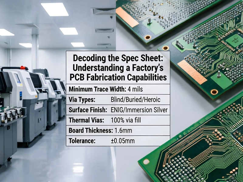
Decoding the Spec Sheet: Understanding a Factory's PCB Fabrication CapabilitiesJune/11/2026
Managing Signal Integrity and Impedance Control in High-Speed Multilayer PCBsJuly/21/2026
Essential Tips for Your First Custom PCB OrderJune/02/2026
Testing Services: From Flying Probe to Functional Testing (FCT)August/15/2026